 scottacrane
Yes, 100W of LED goodness would have been great, but the heat and the power, not to mention size, is too much for the given housing. The 10W chips fit much better in the hole vacated by the old lamp is is plenty powerful enough. I could have also just went from battery to DC booster to LED and adjust accordingly, but I also wanted to run a strip of addressable 5050 RGB LEDs (WS2812Bs,) thus requiring some kind of processor. Hence the Arduino nano.
Another reason I decided on the 10W LED is that it only needs around 9-12v and thus a much smaller DC-DC booster than the more powerful 20W, 30W, and 100W LEDs that require over 30v. After trying several DC-DC boosters with the single sell 3.7v LiPo, the 4A max XL6009 was the only one that worked for me. The 2A N108 (MT3608 on back) did not boost for me.
Given I needed an Arduino to run the addressable LEDs, I can also use it for other purposes. Like PWM the 10W LED. Also why not monitor its heat sink temp (via a LM35) and auto adjust brightness if it gets too hot? Since I have a on board LiPo, why not also monitor its voltage. And since I have addressable LEDs, then use them to display the battery status which I've decided to do after initial startup.
I wrongly ordered a weather proof lighted switch to replace the original, but it was wired for 110v and not 12v. I just got in the replacement, and guess what, its also rated for 110v and not 12v as the eBay listing showed. For now, I'll just live without a lighted switch and press on.
Current status: I have some of the wiring done including the MOSFETs on a board along with their resistors. As you might guess, there is not a lot of room inside the case and stuffing all this stuff is going to be tricky. Will update with actual photos (and not just stock) here tonight. I also need to work out the programming (my profession BTW) on the main LED and temp monitoring as well as the voltage/LED display, and capacitive touch.
 Doubleyou
 Lyon
Lyon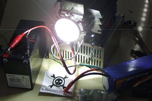
 Yannick (Gigawipf)
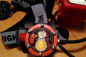
 Jakub Kaderka