 Michael Murillo
The Beginning
When this project started I was moving apartments about every year, so the only firm requirement was that I could fit the server in a traveling rack. Travel racks are most often used for smaller audio gear, not large server equipment, and have about 19" of space between both rails. This eliminated all but a few server chassis as most servers are 25" in depth or longer. It also needed to be large enough to fit a GPU and provide enough power for it, eliminating servers with less than 500W power supplies. Also, I limited myself to used equipment on eBay. As such, the first parts ordered where:
Step 1: GPU Power
I knew from the start that I would need to figure out how to mount the graphics card sideways as a 2U tall chassis would not support a graphics card plugged directly into the motherboard. The graphics card also needed the power pins on the rear of the card instead of the side so that it wouldn't interfere with the case. What I didn't expect was that although the power supply was rated for enough power, it didn't have the right Molex connectors for the GPU. This site has a good overview of the different connectors commonly found on power supplies. The power supply came with:
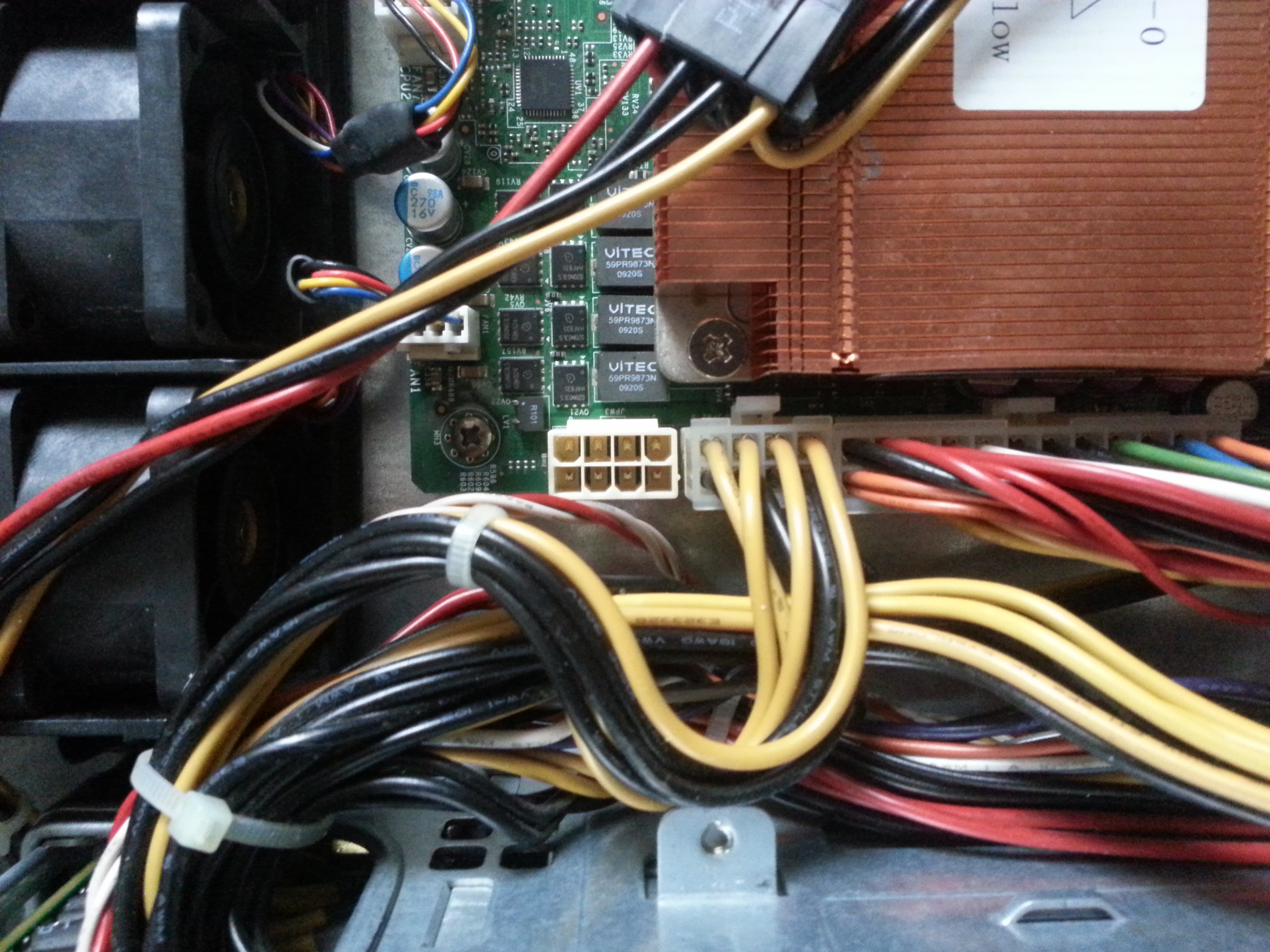
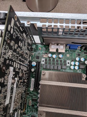
- 24 pin ATX (picture 1 below)
- 2x 8 pin EPS +12V (picture 1 below)
- 4 pin ATX +12V (not pictured, unused on original setup)
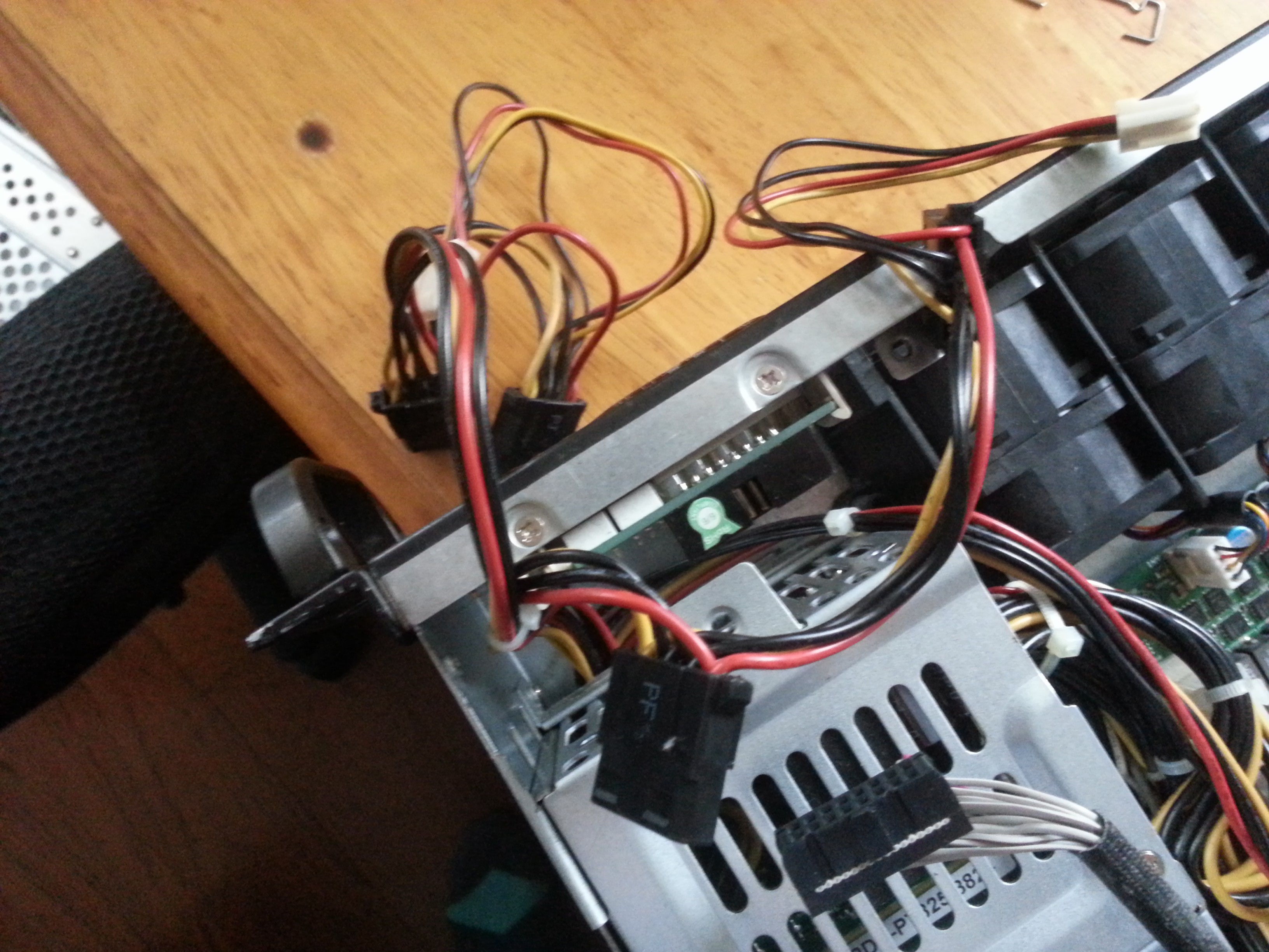
- A few 4 pin peripheral power cables (2nd picture, 1 in use for the HDD backplane)
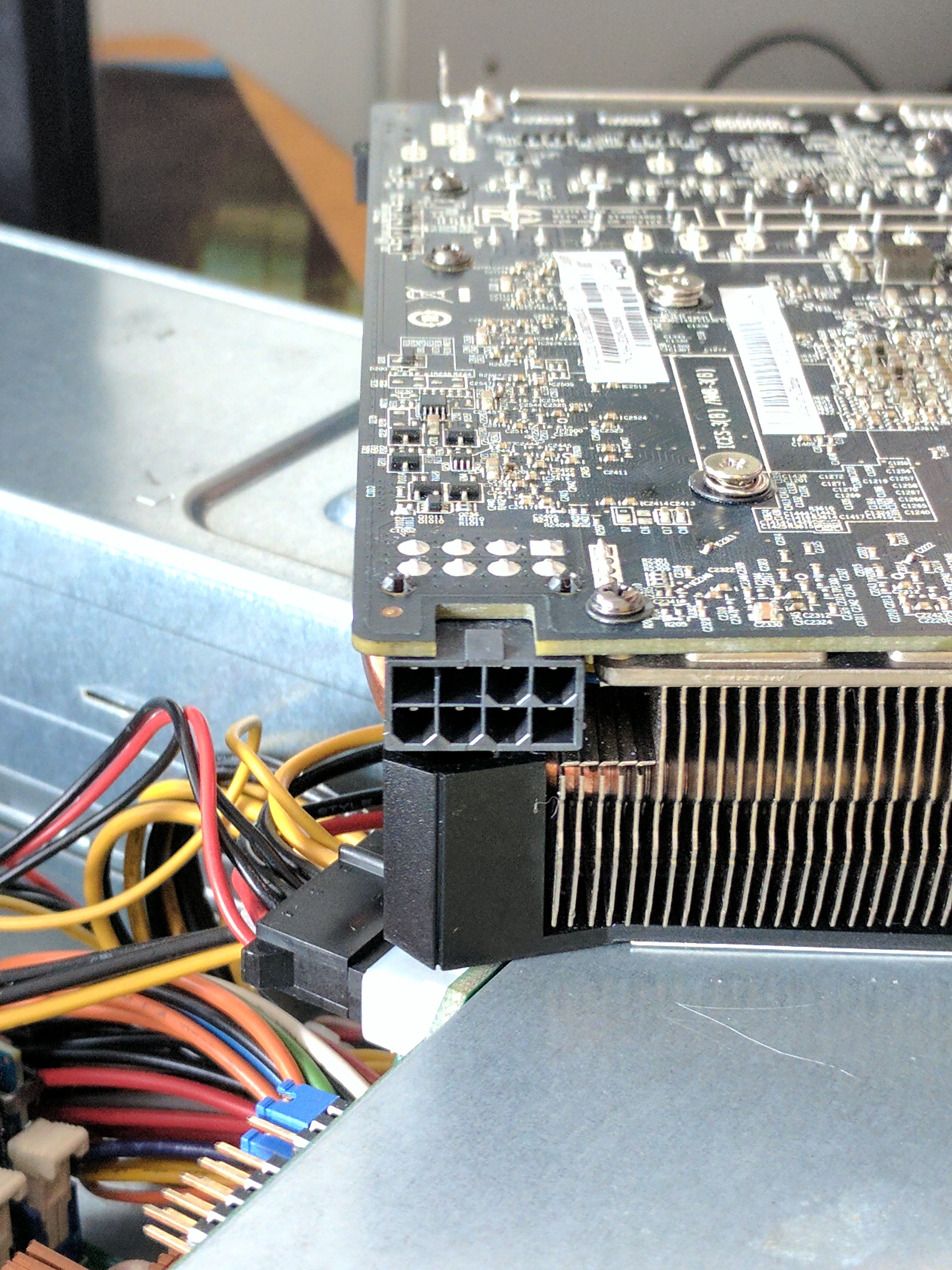
But I needed an 8 pin PCIe cable (3rd picture). So now the question is, will the power supply reliably power a GPU if it was not designed to? 700W should have ample room, but I now needed to dig through PC standards documentation to make sure.
The two relevant standards are ATX (used for chassis and general PC power specifications) and PCI (also referred to as PCIe, used for the data and power connectors on a GPU). Trying to dig around for official ATX and PCIe specifications was not as easy as I thought it would be. ATX was developed by Intel and a lot of their specifications used to be on formfactors.org which is now defunct (it redirects to an intel page with minimal information). Similarly, PCI-SIG, the organization responsible for PCIe specifications, hides their documentation behind a steep paywall unless you join their membership program designed for device manufacturing companies.
Wikipedia had some PCIe power specifications with sources cited to the aforementioned paywall documents. Usually, I trust Wikipedia, but to feel more comfortable I kept searching for something with a more direct connection to the PCI-SIG group. Eventually, I found this electromechanical updates slideshow from a conference, pages 7-11 detail what the different pins of the PCIe power cable do. For those unfamiliar with GPU cards, they come in a few different power variants. Some have no external power and consume only 75W from the motherboard. Others have different permutations of 6 pin and/or 8 pin connectors: the 6 pin variant provides an additional 75W, and the 8 pin variant provides 150W. Reading the previously linked slideshow you'll notice that the only difference between the 6 pin and 8 pin variant are two additional ground pins, not an additional 12V/GND pair. So how do these extra cables provide more power? They don't, they're just for shorting sense pins on the GPU to tell it that the power supply is capable of providing enough current.
The ATX specifications turned out to help determine if my power supply could provide enough power. Servers do use ATX connector standards, but the power supplies themselves are not standard ATX power supplies used in desktop PCs. Instead, they use various proprietary power supplies and proprietary power distributors for fail-over. The user manual for my super micro model is where I ended up finding the information I needed (section B-1). My power supply has a single 12V rail that can provide 58A of current.
Total available 12V rail current: 58A (696W)
Some quick back of the napkin math and a power meter shows that there is plenty of room for the GPU. At this point, the system does not contain an OS, let alone a hard drive. Simply plugging in the PSU consumes 12W. Powering on the server increases this to 80W (not exactly a power-efficient model huh?). Note that this is 80W before DC conversion and the PSU is rated for 90% efficiency. This means the motherboard is consuming 72W. Assuming 100% draw on the 12V rail, this puts us at a 6A of consumption. The TDP of the installed CPU is 80W, and there are 2 of them. Assuming an additional load of 160W on the 12V rail means there could be another 13.3A of consumption (some of the 72W load from earlier is already coming from the CPU, we'd never see the full load in practice).
Total available 12V rail current - CPU/motherboard load = available power for GPU
58A - 19.3A = 38.7A
With 38.7A (464.4W) left on our 12V rail, we have plenty of room for the 225W graphics card plus any HDD's, SSD's, small peripherals, or any additional power required from the motherboard not included earlier.
With all this in mind, I went ahead and ordered a bunch of Molex parts to build a custom adapter with some low gauge cable I already had laying around. The resulting cable had the PCIe 8 pin connector on one end for the GPU, and a 4 pin peripheral and 4 pin EPS on the other to get power from my PSU. Different cable lengths were used to keep the flow of the cable natural, allowing me to tuck it away neatly in the future. I also ordered some right angle SATA connectors with higher gauge wires so I could tuck those cables away from the GPU.
Step 2: Installing a Hypervisor
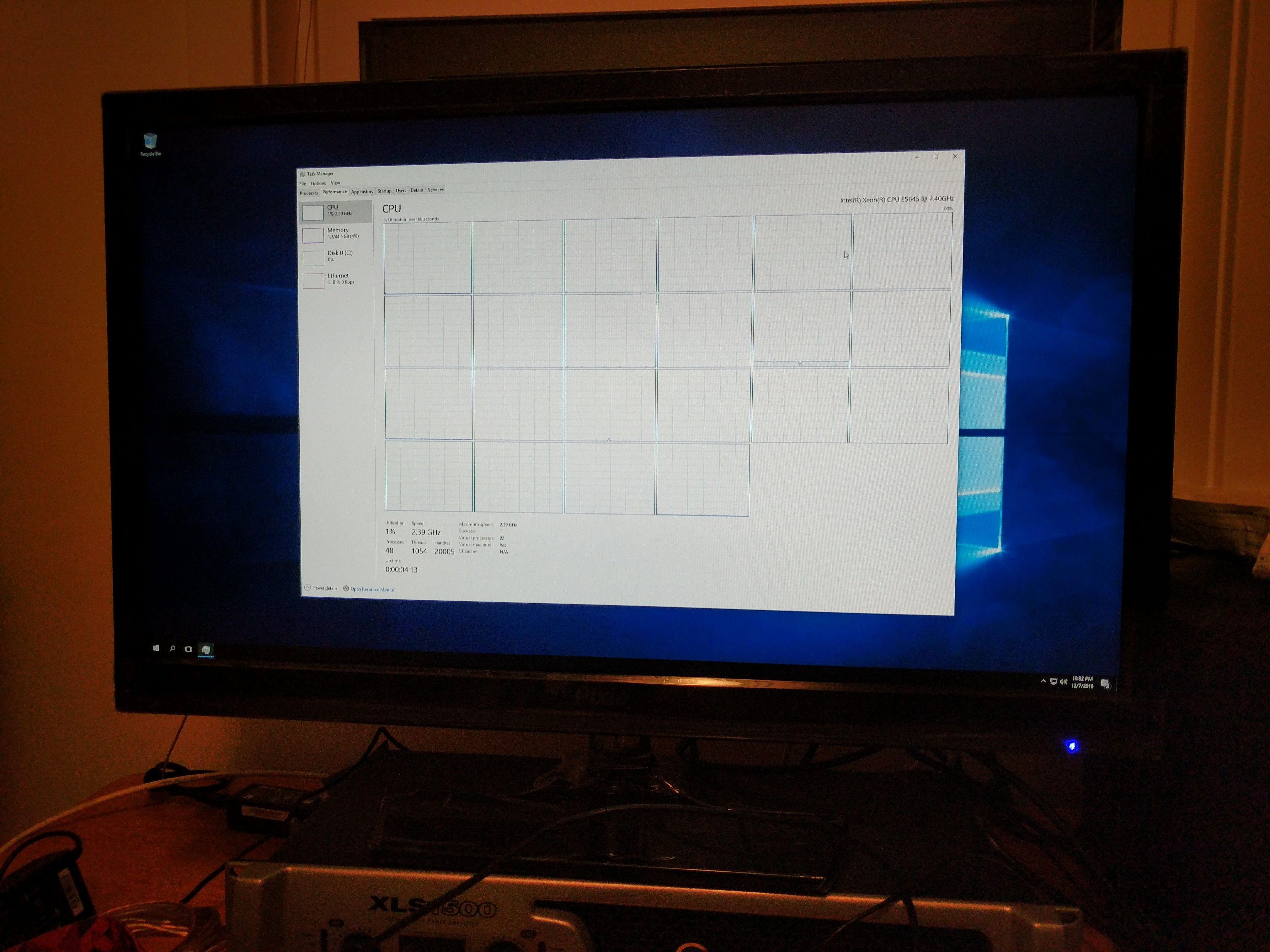
With the GPU installed I was ready to get the server up and running. I wanted the main operating system to be a hypervisor with most applications installed on dedicated Virtual Machines (VM's). There are many hypervisors available, but I ended up choosing Unraid since their product is tailored towards gaming computers and media servers. After some fiddling around with settings I successfully got a Windows VM installed with the GPU "passed through":
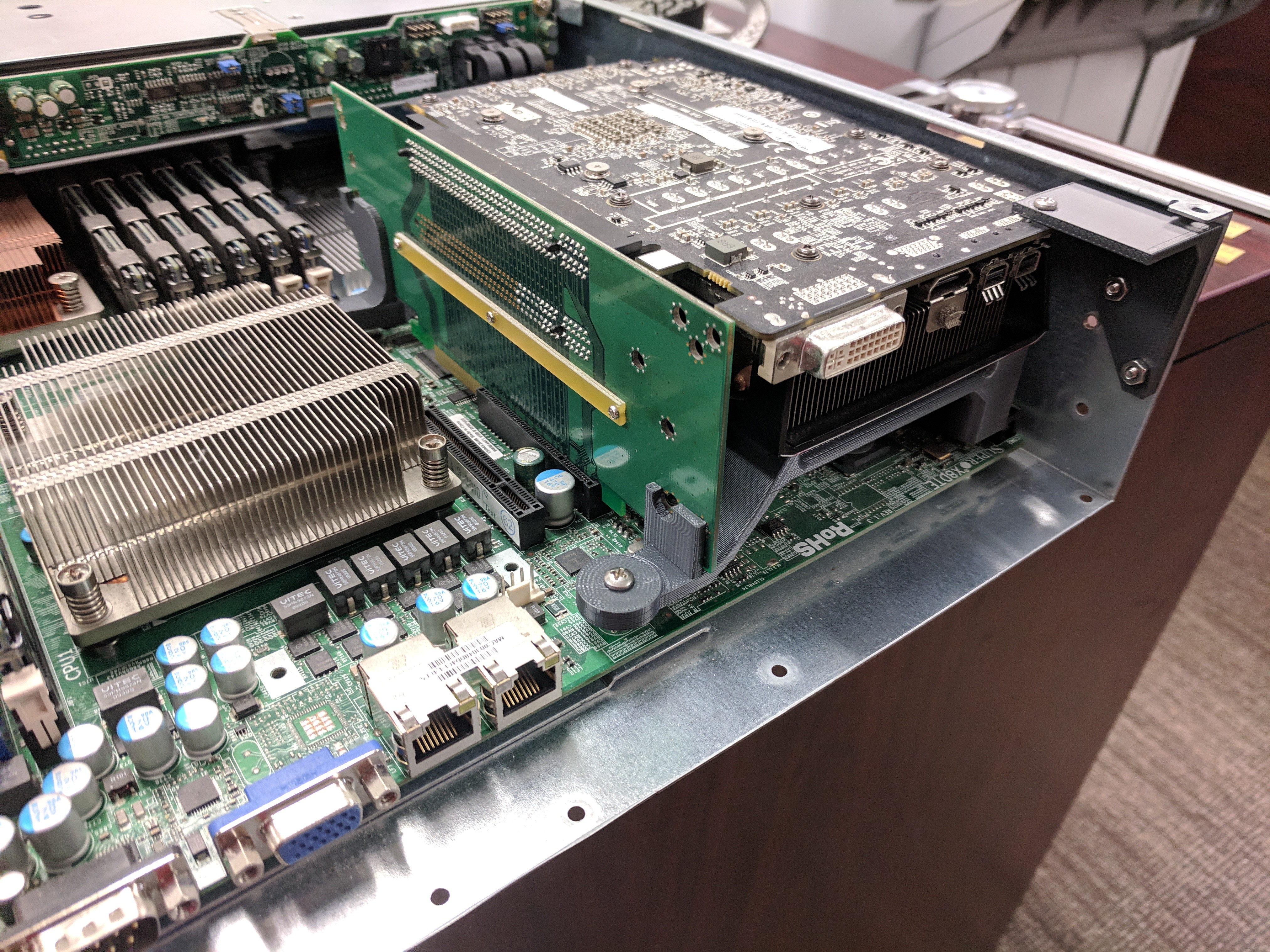
Step 3: Mounting the GPU
"Hey wait a minute, that graphics card doesn't even fit!" I know... that's the fun part! The only thing I need is a right angle PCIe adapter and something to physically hold the card in place. Initially, I thought about creating a PCB and read through the extensive signaling requirements for PCIe. I decided against this and looked at commercially available options. 3M has a rather pricey flexible cable assembly that would do the trick. However, there are plenty of used server parts on eBay that would also work. I ended up settling on this rigid right angle adapter (manufacture page in case the eBay page gets removed).
For the physical mounting, I took advantage of the fancy Stratasys FDM printer available at work. Unlike hobbyist printers, this one has a heated chamber that allows for thin structures to print without warping. The filament also comes in these horrible cartridges with DRM that prevent you from using your own filament. The cartridges even have an expiration date! This works in my favor though as my employer doesn't mind if I use close-to-expiring cartridges for personal projects like this.
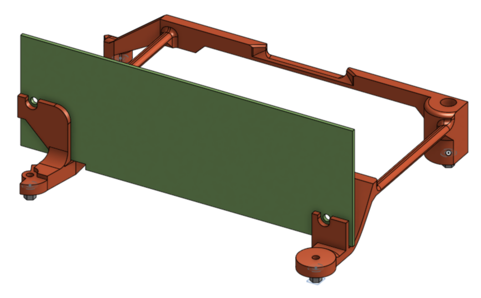
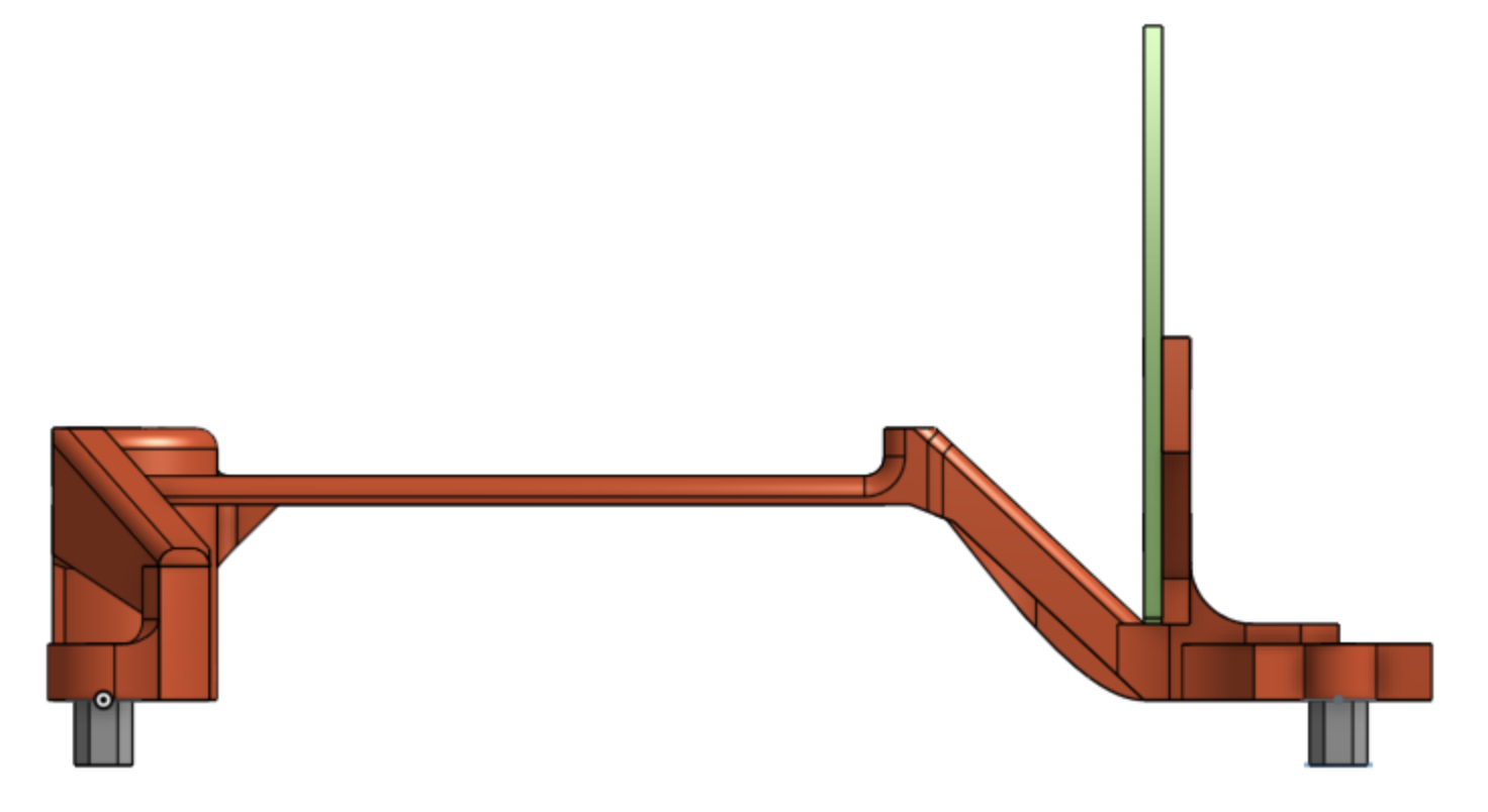
For the actual design itself, I measured the E-ATX motherboard mount points and position of the right angle PCIe adapter, then modeled them in CAD. From there I could work backward and design a support structure off of known dimensions. The old "measure twice, cut once" phrase helped in this scenario as not all the mount points on Supermicro's E-ATX motherboard match the E-ATX standard. With only 2 or 3 small edits I was able to get the following parts modeled, printed, and installed:
At this point, the project was ready for use as a media server and gaming pc. It was pretty noisy though. The quick fix was running it in my workshop area and mostly playing games with friends in the living room using a steam link. I used it for almost a year this way. The noise never bothered me too much as I used headphones most of the time. Although the project never really felt "done" because of it.
Step 4: Dealing with sound
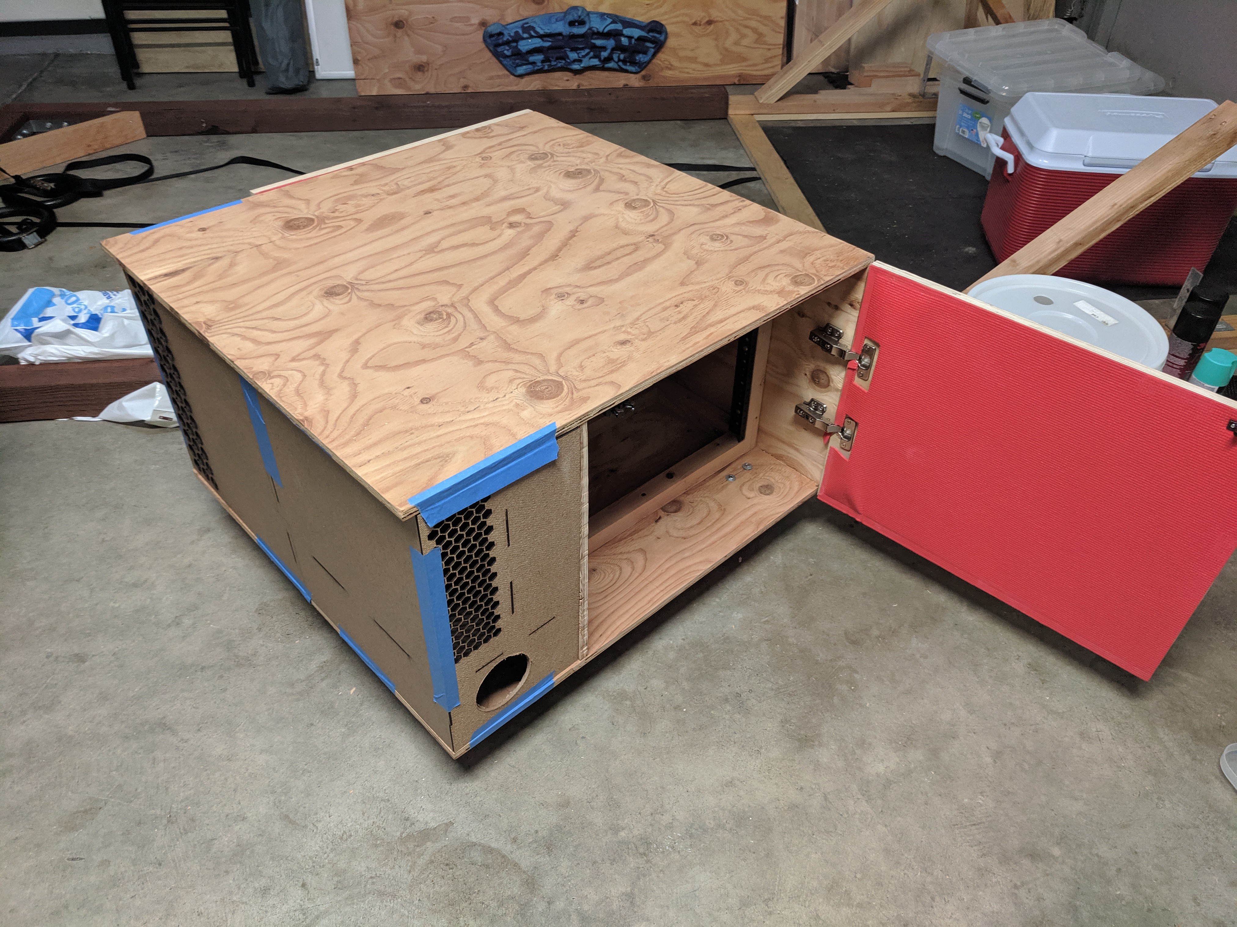
In 2017 I moved into a different apartment with a 2 car garage which let me collect more tools and build larger projects. One of the first projects I tackled was creating a wooden rack with an air baffle so I didn't have to worry about the fan noise. For the air baffle, I copied a design that I saw at work. Some of our electrical systems have noisy cooling systems and are used by operators in small rooms. To combat noise the systems have a "zig-zag" air baffle near the fans which allows for mostly unimpeded airflow yet forces the sound to go through layers of material:
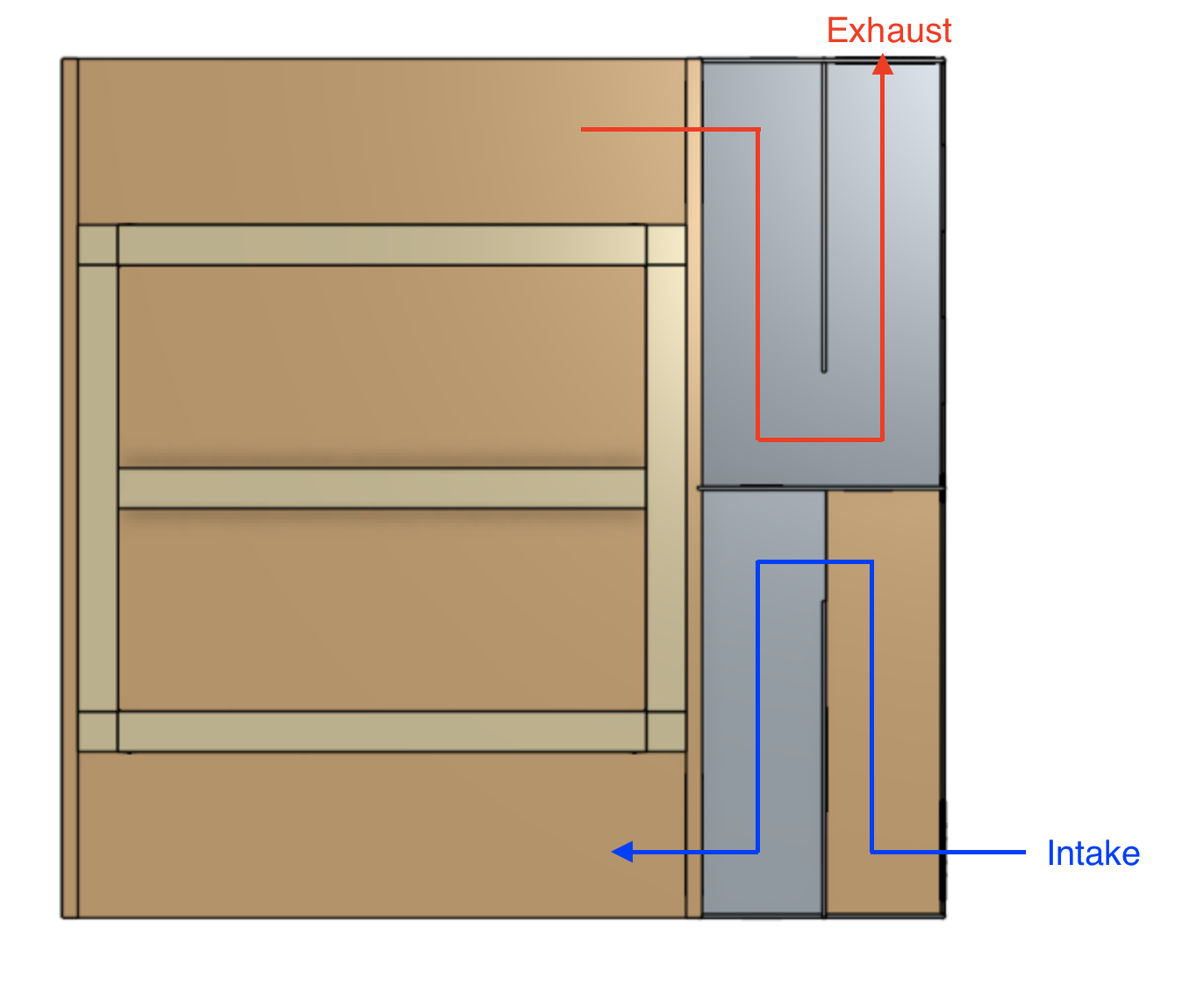
Again, I used CAD to model it first before building it. Most of the server rack was built in my garage, but the sound baffling was a good excuse to use the new laser cutter at work. 😎
All in all, I'm happy with the use that I got out of the server and the things that I learned from building it. I've detailed some of the things that went well, and some of the things that I would do differently below:
What went well:
- Mounting the GPU sidewise worked well, was fast, and cheap. I'm not sure why more commercial cases don't do this, it makes the overall case size much smaller. Even though the fan was pointed towards the motherboard I never had any thermal problems.
- Creating the Molex cable also worked great. The custom length let me neatly tuck everything under the hard drive assembly without any awkward excess cable.
What I would do differently:
- Portable power may have been my goal, but ultimately the server chassis was still too heavy for my liking. Many small form factor PCs cut down on weight but none of them are rack-mountable. For a future revision, I would either modify a blank rack mount chassis or create my own from scratch. This would also let me fit a longer graphics card.
- The rack cabinet and air baffle were large and bulky. It worked well, but again, was simply too heavy. I would rely on quieter fan parts from the beginning to avoid having an air baffle.