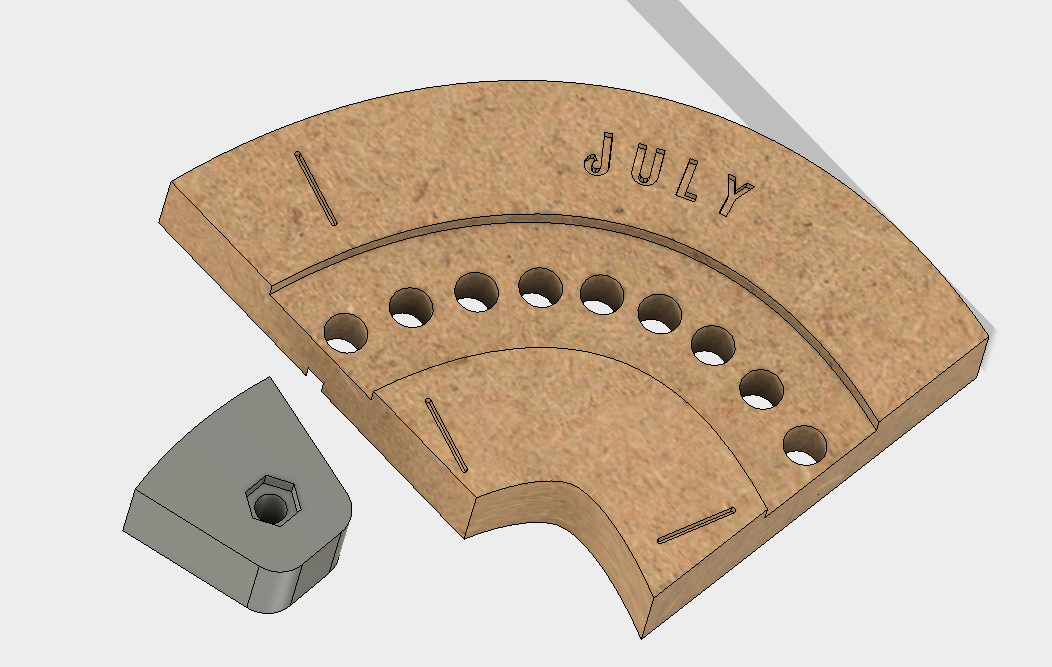
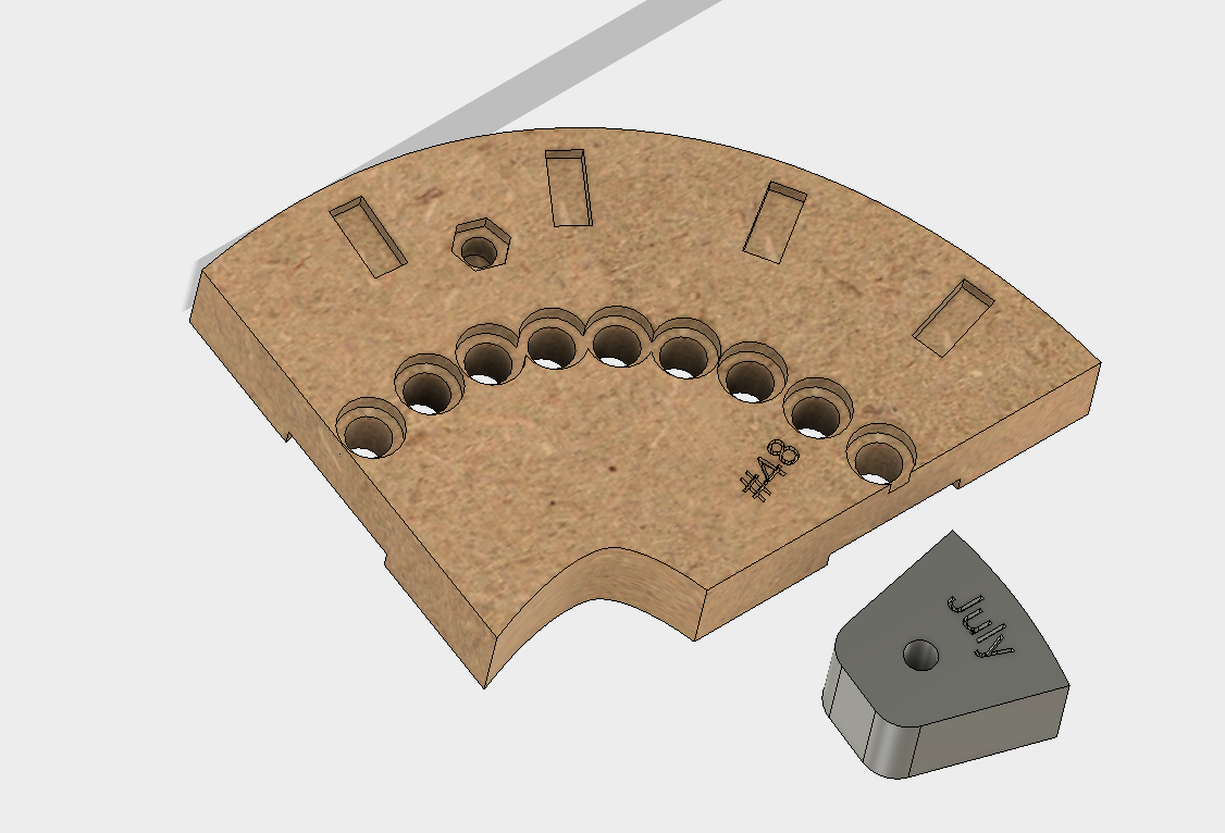
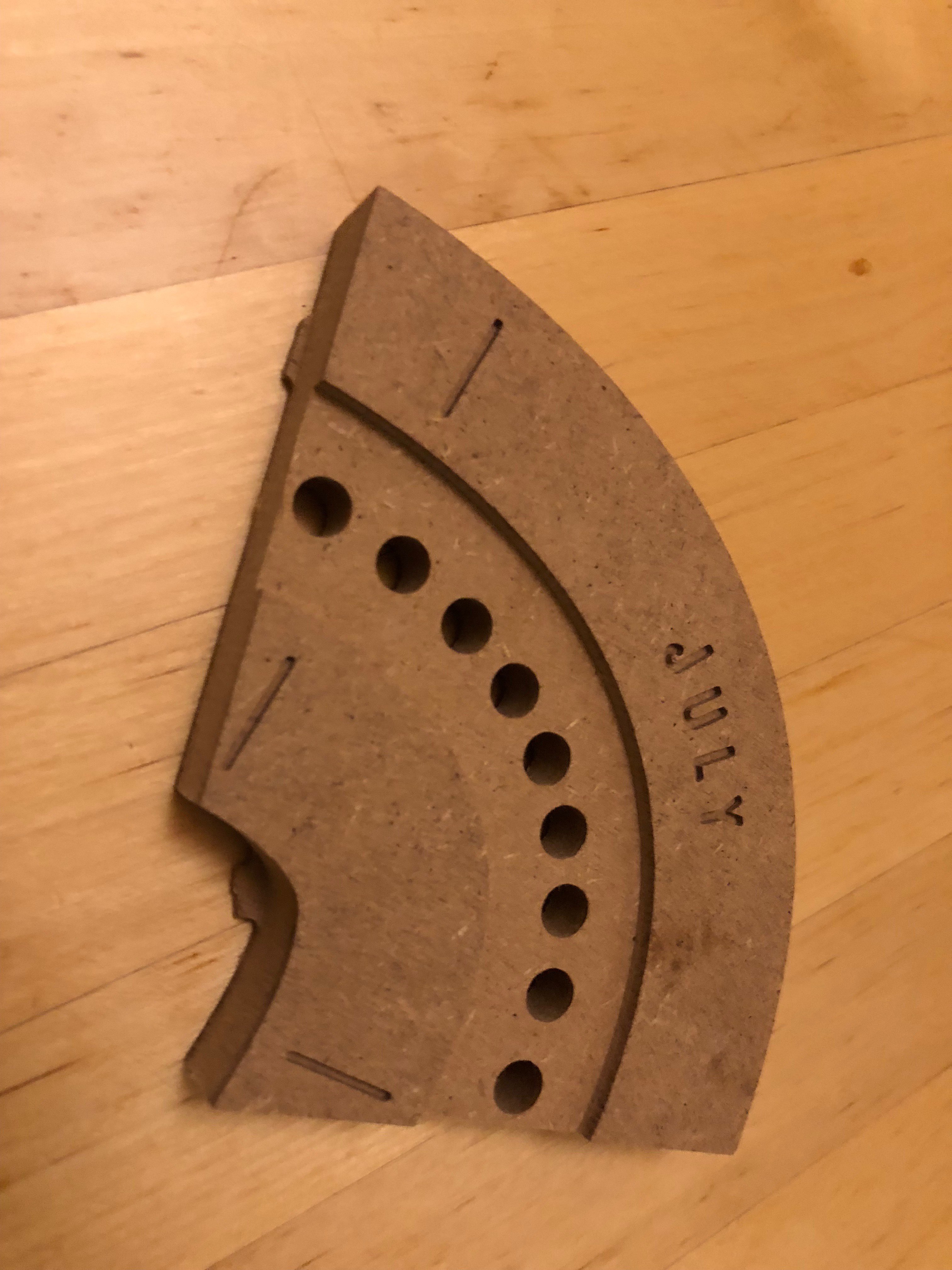
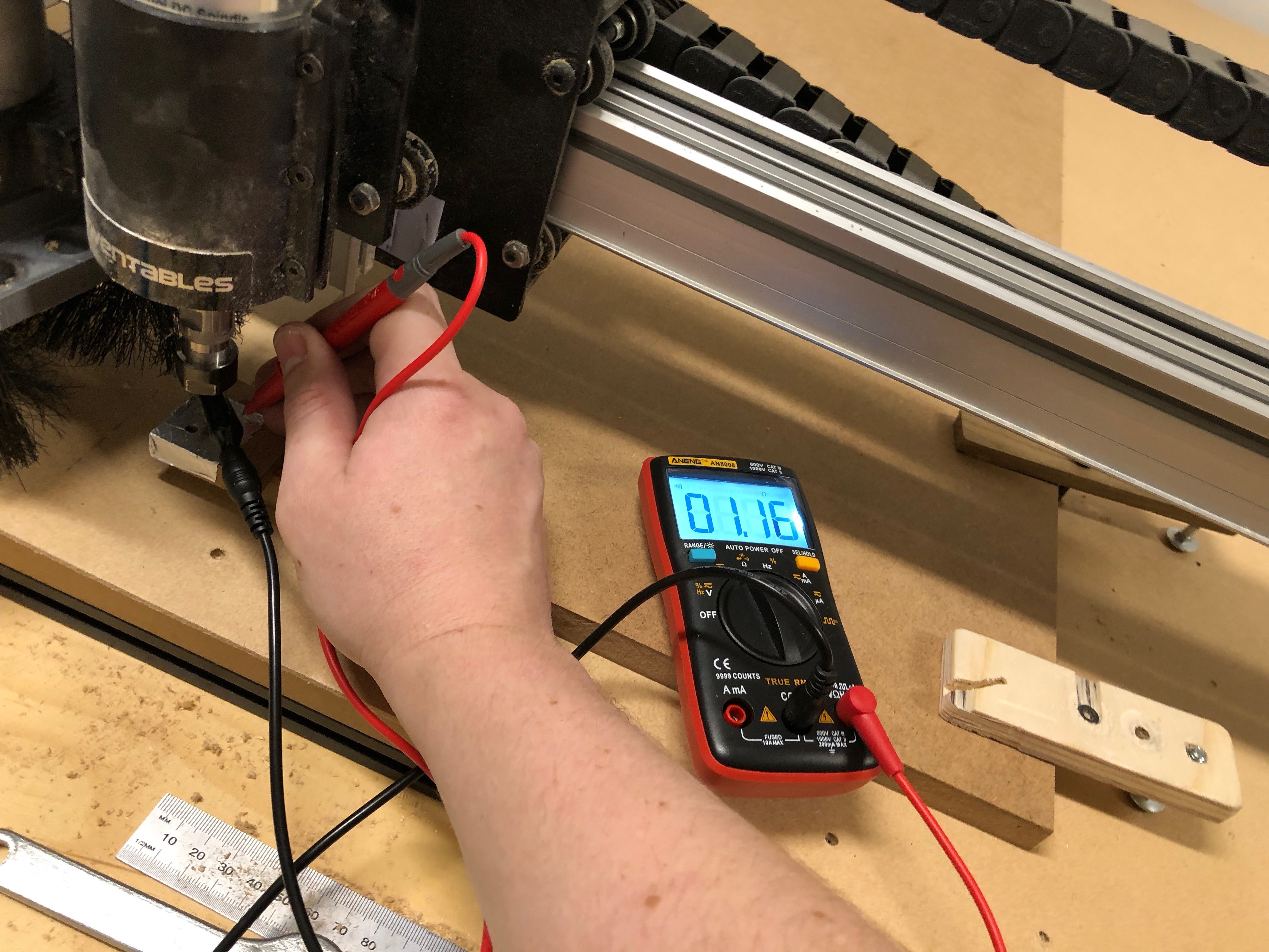
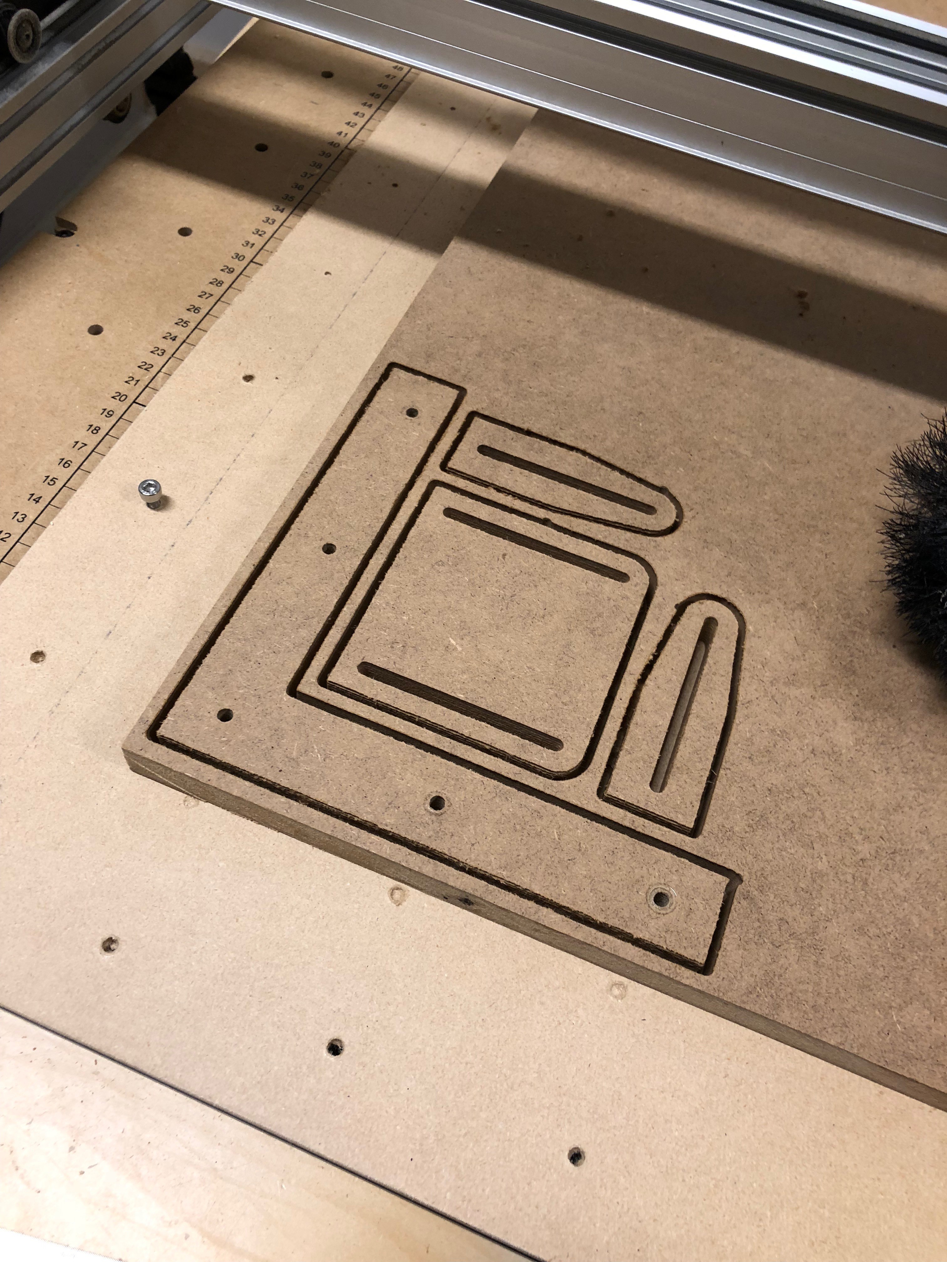
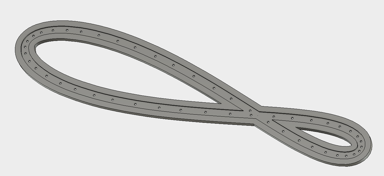
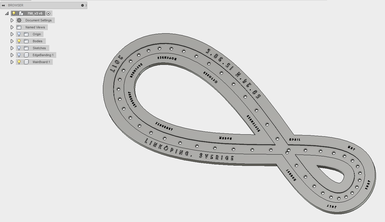
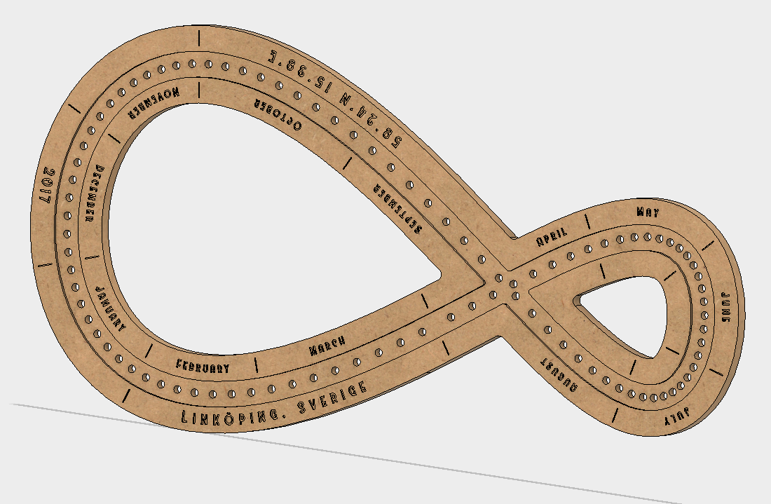
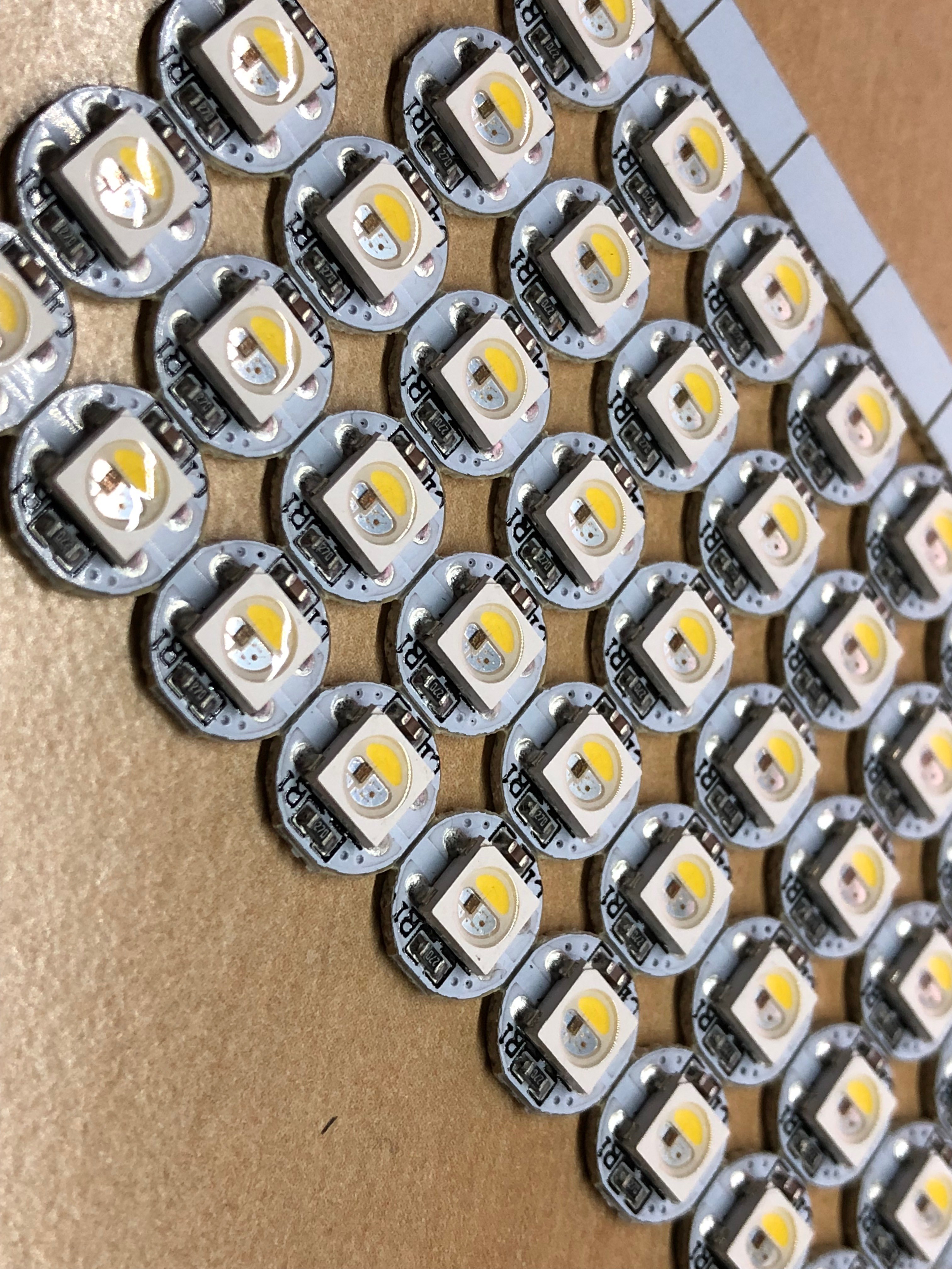
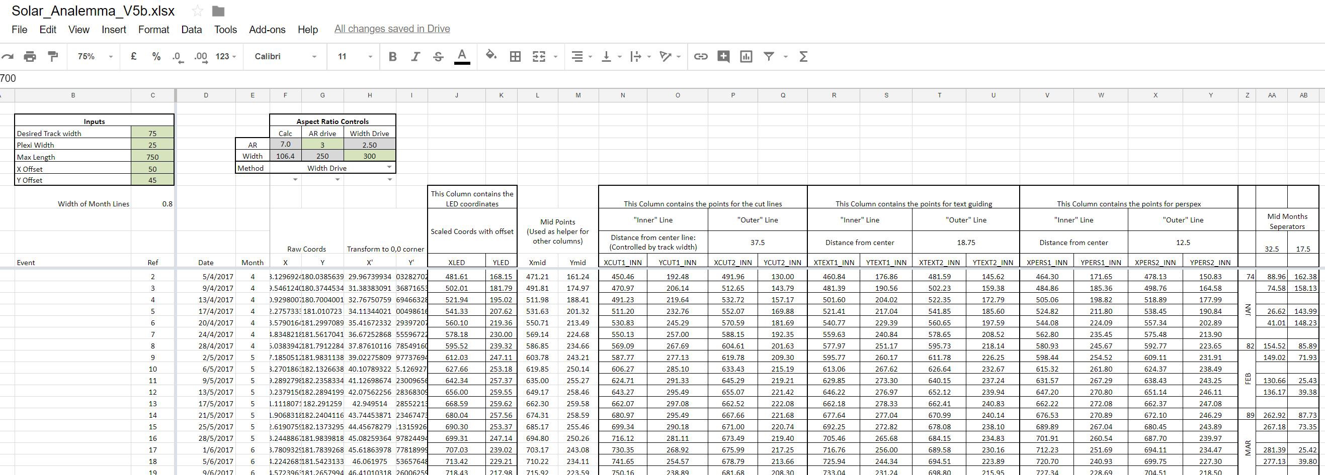
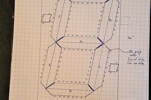
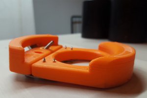
• Log 6: Time to start cutting... again.

    doigal04/22/2018 at 20:13 0 comments

    After the lessons from the first test block, it was time to get a sheet of MDF, which should be the final material that the light would be cut from. 

    A few other decisions were made after the original test block:

    • The slots to hold ribs in case a side piece to stiffen the MDF were changed so that they didn't go to the edge. This was done in case its not required, it just gives me options for later on.
    • A nut trap was added so an M5 hook could be added at 4 corners to hang the light
    • All helper text on the back is to be engraved (done to save the 0.8 endmill and for reducing machine time)
    • All text on the face side to be pocketed with the 0.8mm, as its clearer to read

    And so after all the changes were made in the main model, a new test block (v2) was made in 360:

    With the touch block for positioning this was much easier to get the double sided accuracy that was missing from the first block. The upcut endmills gave me nice clean edges as well, a good investment. Thankfully I had ordered spares, as a stupid mistake from me killed one of the 0.8mm ones.

    I was really happy with the end result:

    So moving forward:

    • The Nut trap wasn't quite deep enough
    • The plexi still needs to be done and checked
    • Otherwise, time to do the big cut!

  • Log 5: The Extra Helpers

    doigal04/22/2018 at 19:59 0 comments

    I found out that I needed three little helpers to get the most out of the CNC.
     
    Quickly I realised that the method of setting the z height by hand, as well as the positioning of the block (double sided machining for first CNC project is keen.) by eye just isn't going to be good enough. Since its not my CNC machine just to hack an automated touch block onto, I had to do a low tech solution.

    It took all of about 30 minutes to design and cutout a tiny corner block from MDF and cover it in tin foil. This I can slide onto the bottom left corner of the stock, and with a multimeter set to continuity testing, slowly jog the end mill into position. Having measured the block with calipers beforehand, its simple to define the offset to the corner of the stock. Each axis is 'homed' using this and G92 commands. Its not perfect, but its good enough.  

    The second helper is just some mounting blocks for the initial drilling. The mounting solution is to drill out a 75x75mm M5 bolt pattern to match the X-Carves wasteboard, but since I use the CNC to do this, the initial stock needs to be mounted first. This is nothing more than a fixed corner piece and some sliding adjustable ones to lock the stock into place.  

    The last helper is a waste board with the M5 holes drilled out so it just acts as a cover for the x-carve. Nothing fancy about it at all.

    All three items were super quick to model and cut, and hopefully will last a lot longer than this project!

  • Log 4: Time to start cutting

    doigal04/22/2018 at 19:53 0 comments

    Before committing to a large block of wood (and the milling time required to cut it) , I wanted to do a few test blocks to properly get the right parameters for tooling, materials, finishing, etc. 

    The idea with the first one was to check the different machining processes - would the 0.8mm endmill or the v engraver work better, size of the text be OK, make sure the edges come out clean, etc. A difference operation in Fusion gave me a small section that was going to tell me what I needed:

    An hour of CNCing later at MakersLink, and I got this:

    So what did I learn?

    • The LED holes are the right size, no need to change.
    • Plexiglass tolerance TBD - I still need to get the plexi.
    • Packing Plywood is absolutely awful for this!
    • The smaller text on the front side is way too small for the 0.8mm cutter. Also the engraving isn't as clear at either size, and again looks horrible in this material.
    • Hitting the glue line for the plexiglass pocket gives a very 'interesting' pattern thats not consistent at all.
    • Based on the above, and the struggles finding good quality plywood locally, its an easy decision to swap to MDF instead
    • The cheap chinesium upcut endmills leave horrible tearout on the top surface. Part of this is due to the plywood, and part is due to the upcut format. Time to order some good quality downcut endmills instead. 
    • Do NOT forget to home properly when doing double sided machining!

  • Log 3: Design, The Hard Way.

    doigal04/22/2018 at 17:10 0 comments

    The design process is a little convoluted, but I think this is mostly due to my limited CAD experience.   


    The excel sheet (See Log 1) generates all the points based on the number of LEDs I can fit in, and then transforms this to the desired aspect ratio. A few other things are done here as well - Construction lines for the text, outer and inner lines for the wood and the perspex lines are all created mathematically. These are output as points into seperate csv files.
      
    Fusion is then used to import the CSV data as splines in sketches. The 3D model is built off this data. As fusion struggles with complicated text (text along the spline), the final face sketch is then exported to inkscape for the text, and then reimported back into fusion, where the text can be 'extruded' into the face.
     

    The big problem with this is any mistake or update at the start means going back and repeating the whole process. It works, but its not ideal.

  • Log 2: 48 vs 96, LED selection

    doigal04/22/2018 at 17:07 0 comments

    So the original plan was to keep it small, have 48 LEDs and the standard ws2812 neopixel RGB. You can get these prewired on a strand of 50. After testing one of these, it just didn't feel bright enough, there wasn't enough resolution for any of the animations that the original had, and the white (Full power to all three channels) didn't look quite right.

    The solution to most of these problems is obvious - MOAR LEDS!!! I found out that keeping it at a multiple of 12 made life easy for having a roughly even number of lights per month, and the LEDs got too close at anything beyond 96 within the limits of the X-Carve that I had access to. So, the choice was made by the constraints - 96 LEDs it is.

    The whiteness of the light is solved by changing from WS2812 to SK6812 RGBW LEDs. 

    An early 48 LED design with a high aspect ratio.

    Closer to the final design layout, still with 48 LEDs:

    The Final design concept:

    A strip of the SK6812 LEDs

  • Log 1: Maths, Points & Splines

    doigal04/21/2018 at 20:47 0 comments

    The first issue that needed to be solved was to calculate the accurate solar positions.

    The position of the sun at any time and location can be calculated thanks to whats known as the Equation of Time.

    Thankfully, NOAA have an Excel sheet which takes location, timezone, dates and local time as inputs, and gives the Solar Analemma (amongst other outputs)  for the entire year.  Whilst this is great, I don't have the room for 365 LEDs, so I have to scale this down a little. Eventually I settled on 96 LEDs, which worked out to 1 LED per 3.8 days.

    A problem that comes up here is that the true shape of the resulting spline is extremely narrow and long (An aspect ratio of 7:1), which isn't the most practical of shapes to use as a light. A little artistic licence was taken to bring it down to slightly more square ~3:1.

    Now that the LED points are defined, and wanting to avoid any extra work in Fusion 360, its easy from here to mathmatically offset the line generated from the LEDs to generate the lines for the wood cuts, the perspex inset and construction lines to wrap the text onto.

    These point files are then imported to Fusion 360 as splines for the 3D part of the modelling.