Jeff Taylor
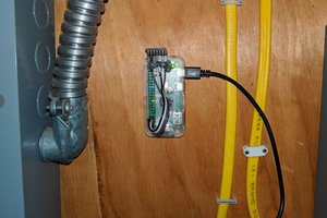
Due to requiring AC power to operate devices such as heaters and lights, I am dropping my original plan to make this project solar-powered. The new plan is to have a device which will always be on, sending periodic updates to a web server so that the greenhouse conditions can be logged and viewed online. The code will support up to 16 devices controlled by a bank of relays and allow setting unique conditions to trigger each device.
0%
0%
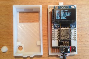
ESP32 Greenhouse Monitor
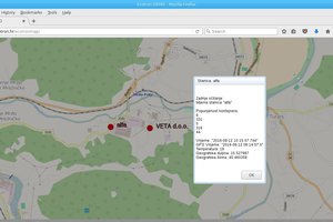
Collect temp/humidity, soil moisture, sunlight data to be stored on local web server
Become a Hackaday.io member
Already have an account? Log in.
Just one more thing
To make the experience fit your profile, pick a username and tell us what interests you.
Pick an awesome username
hackaday.io/
Your profile's URL: hackaday.io/username. Max 25 alphanumeric characters.
Pick a few interests
Projects that share your interests
People that share your interests
 mikrotron
 Capt. Flatus O'Flaherty ☠