 U.S. Water Rockets
This mod breaks with the tradition in this project of doing everything at minimal cost. There's simply no getting around the fact that the Z stepper motor setup in the early Monoprice Select Minis which were produced, caused a lot of issues with Z-wobble and banding artifacts in prints. I was fortunate to come across a used Mini made in the summer of 2016 that exhibited some of these issues, and I was curious to find out if replacing the Z-Axis motor with a NEMA17 motor with an integrated Leadscrew would help. I also hoped that it would speed up the movement of the printer in Z moves, because the stock motor is so slow that configuring the slicer to perform Z-hops on retract actually makes blobbing worse because the Z movement time is long enough for the nozzle to drool. This project shows how the mod was done.
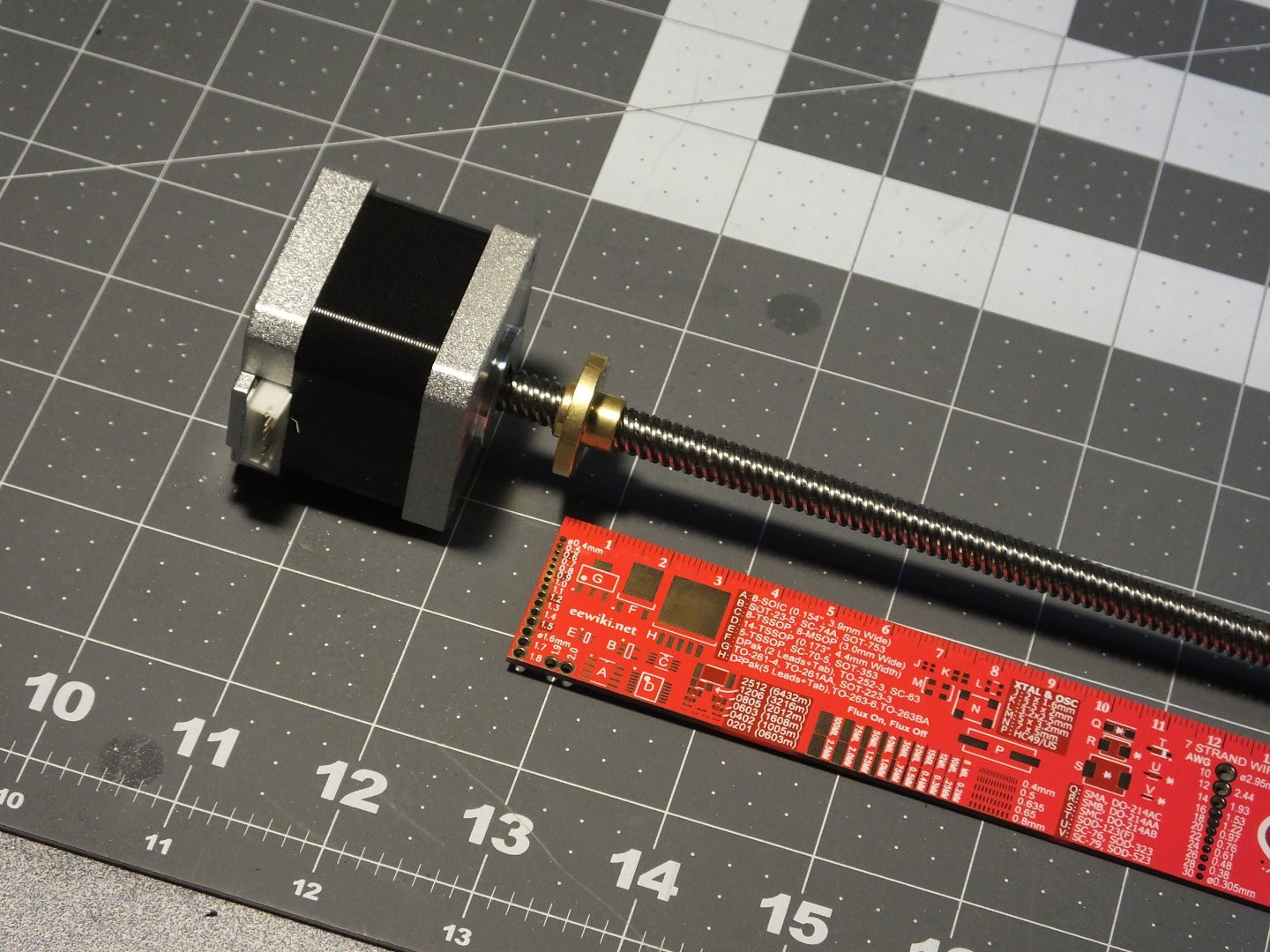 The first thing you need is a NEMA17 motor with leadscrew with a matching nut. I was able to find several sets of them on Amazon.com, and they all seem to be made as upgrades for the Prusa I3 and clones. That means they all have a 300mm long lead screw. This value includes the portion of the screw inside the motor, so it's really about 260mm long. This is actually too long to fit inside the Mini. Note that you can probably get away with a separate motor and leadscrew using a coupler to join them. There should be plenty of room for the coupler under the X-Axis gantry. There must be a standard footprint for the nuts on these lead screws because the hole pattern in the new nut matched the holes in the X-axis gantry on my Mini exactly.
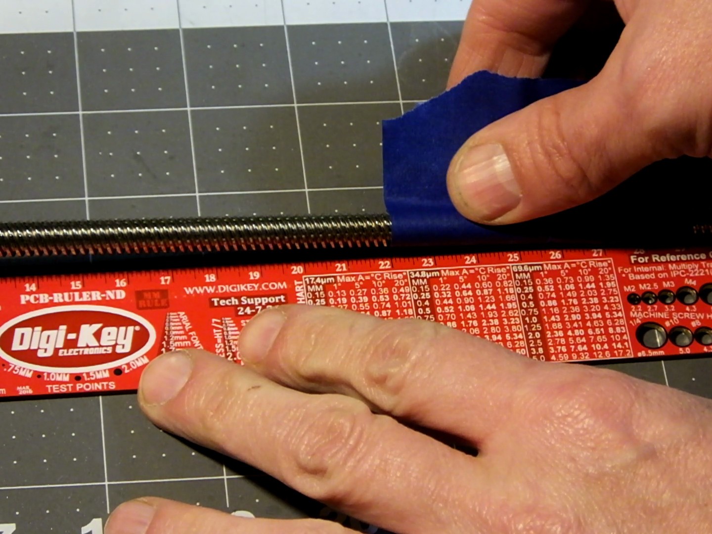 Through some careful measurement and calibrated guesswork, I determined that the lead screw for the Mini with this modification should be 220mm in length, so I measured the correct distance from the top of the NEMA17 Motor, and marked the spot to cut with a piece of tape I happened to have laying around.
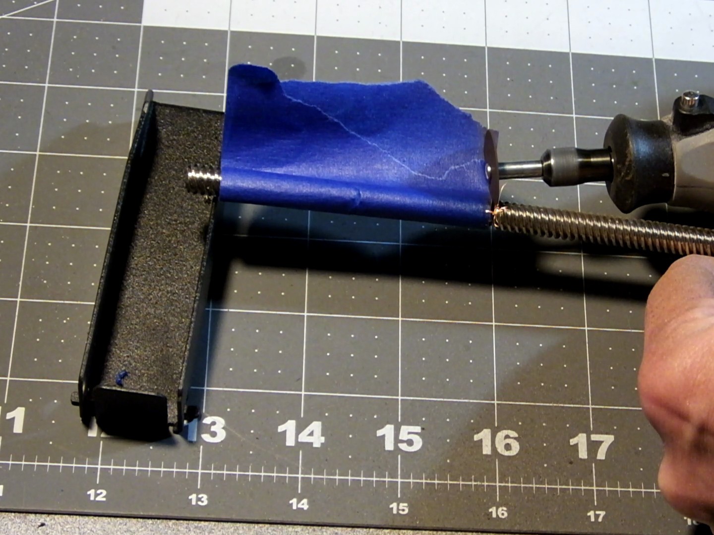 I used a rotary tool with a cutting wheel installed to cut the leadscrew to the proper length. I tried to do this as carefully as possible and as straight as possible, by rotating the leadscrew by hand as I cut into it around the perimeter and toward the middle until the excess part fell off.
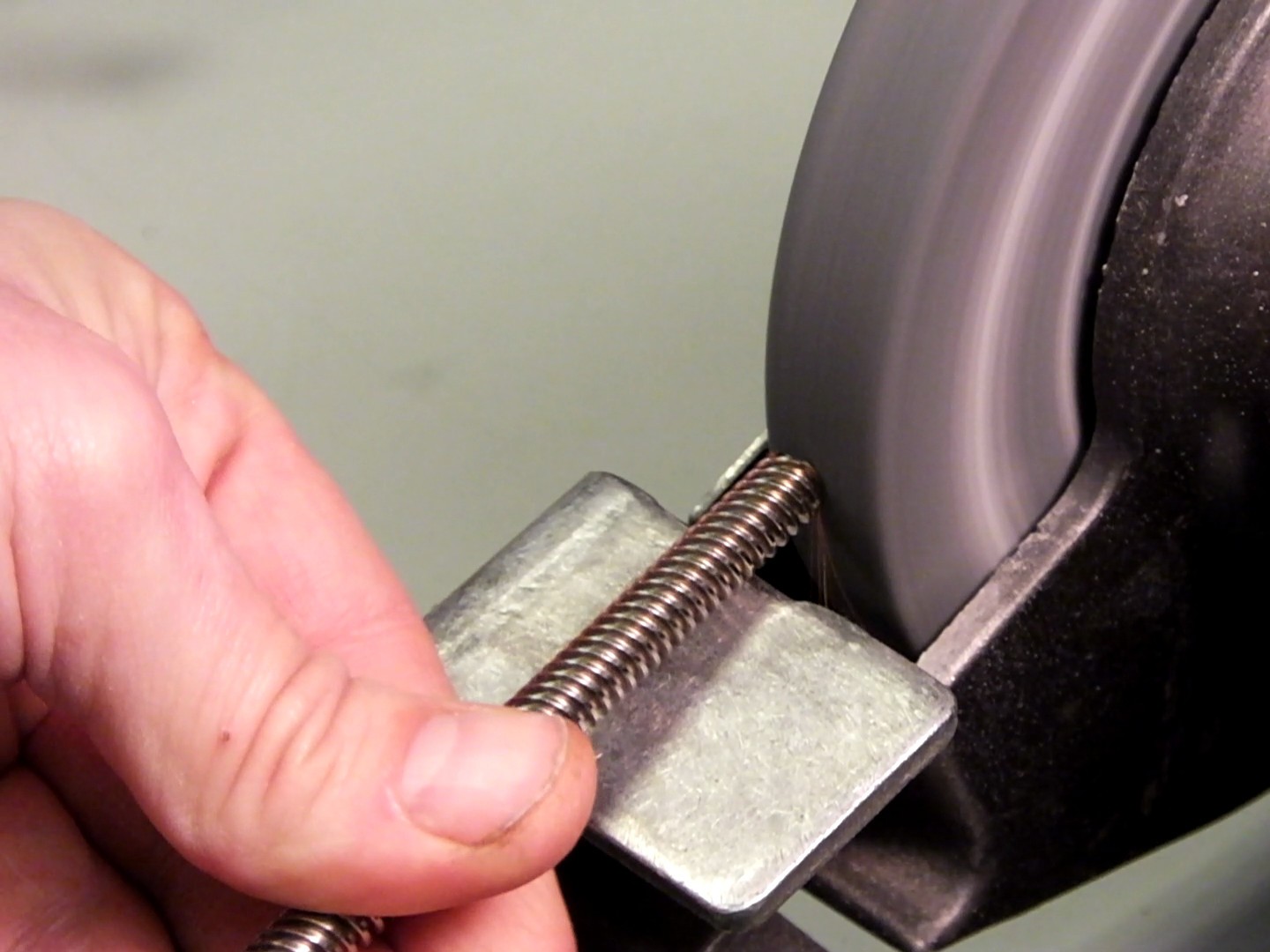 The cut end of the lead screw was a little jagged and had sharp edges and it was difficult to get the nut to thread on, so I used a bench grinder to round off the end of the lead screw to get rid of the sharp edges. Now the not would go on and off easily. With the motor prepared, it's time to dig into the guts of the mini and swap the motors and lead screws. I've already detailed how to remove the existing lead screw in my previous project entry: https://hackaday.io/project/14823-monoprice-select-mini-maximum-3d-printer-mods/log/51880-dont-go-wobbly-on-me-now and how to remove the X-axis gantry and Z-axis rods in this project log: https://hackaday.io/project/14823-monoprice-select-mini-maximum-3d-printer-mods/log/45659-adding-3d-printed-z-axis-rod-stabilizers. You will want to perform the Z-axis stabilizers and install them with this upgrade because these mods compliment each other and most of the same disassembly steps are required for them both.
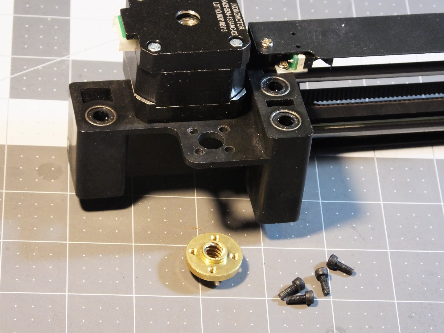 The next step is replacing the lead screw nut on the X-axis gantry with the new one that came with the leadscrew. Take out the 4 screws from the existing nut and swap in the new nut. You will need some M3 screws to hold the new nut in place. Note that the nut can sit on top of or below the gantry. If you use a separate motor and leadscrew with a coupler, you will possibly have to put the leadscrew nut on the top of the gantry to leave space for the coupler under the gantry.
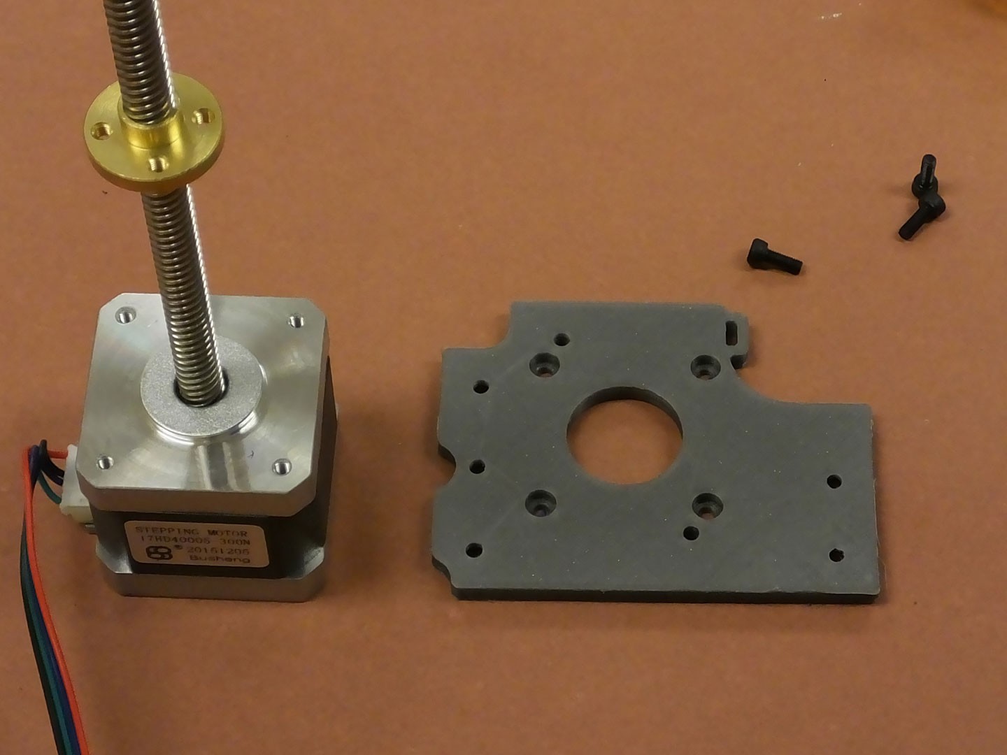 You should have a printed NEMA17 mounting bracket for the Z-axis already printed and ready to install. If not, grab the file from our Thingiverse page here: http://www.thingiverse.com/thing:2199805 and put your mini back together and print it out. ;-) The bracket plastic doesn't matter (as long as you don't use flexible filament) because it should not get too hot. You will want to use thick (>1mm) walls and top/bottom with heavy (>25%) infill to make sure this part is stiff and does not flex. Be sure it is not warped when you print it too. It has to be perfectly flat.
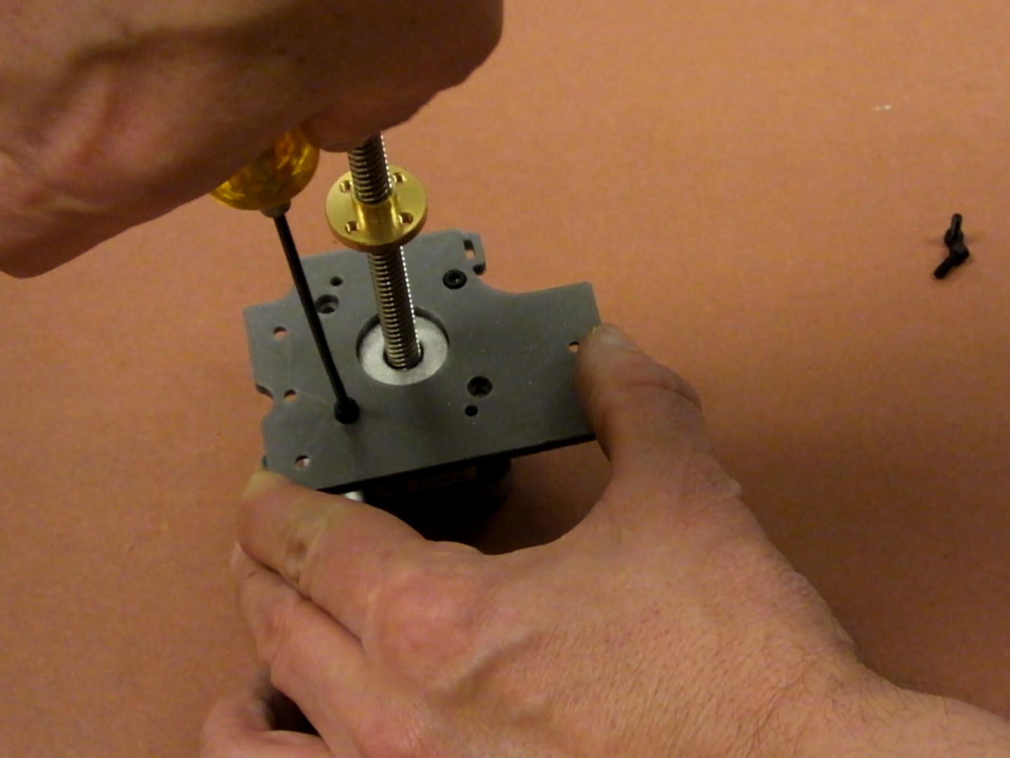 The bracket mounts on top of the NEMA17 motor and has recessed countersunk holes for four M3 socket cap screws. The bracket only works in this orientation, so be sure the screws are in the countersunk holes and are not bottoming out in the motor. They screws have to be secured to the plastic so the motor cannot move. Different motors seem to have different depth threaded holes so try a few screws until you find ones that don't hit the bottom of the holes in the motor.
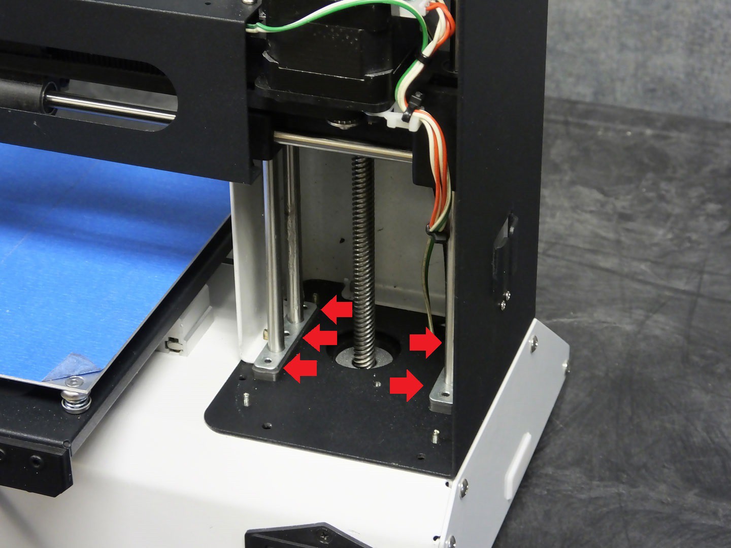 Reassemble the Z-axis rods and X-axis gantry as described in the "Z-axis stabilizers" part of this project, and insert the NEMA17 motor into the chassis from below. Do not install the screws in the Z-axis rod ends shown here with red arrows just yet. You will also need to start the leadscrew threads into the leadscrew nut on the gantry and turn the leadscrew by hand until the NEMA17 motor can slide in place without the gantry hitting the upper extent of travel.
 You can now install the screws through the motor bracket and into the z-axis rod stabilizers, holding the rods and the motor to the chassis and also in perfect alignment to each other. You may need slightly longer screws for this as the screws now need to go through the motor bracket.
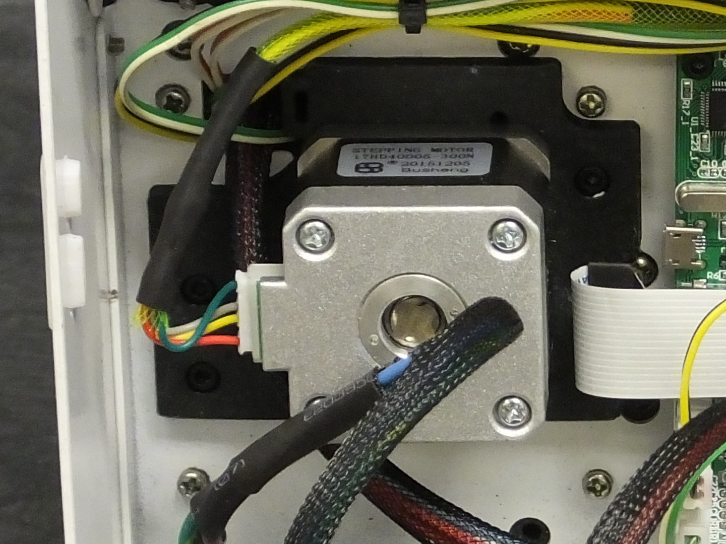
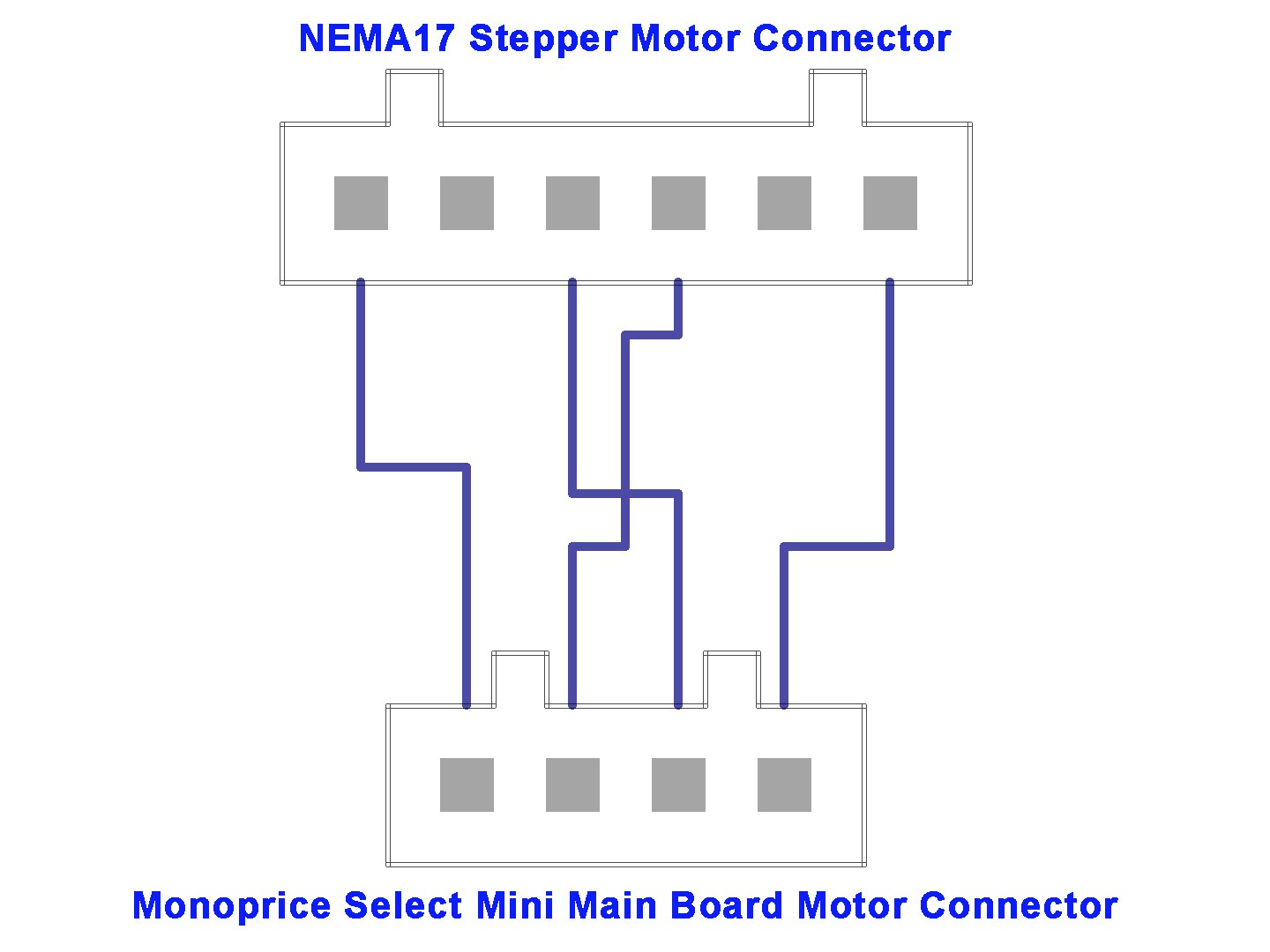 The last thing you need to do is wire up your motor. If your motor has wires connected directly to it, you may have to do a little digging around the MPSM facebook Group to find out the correct way to wire your motor. I picked a motor with a cable that plugs in so that I could use the cable that came with the printer, only I was surprised to find out that the old motor and new motor had different plugs. Fortunately, the NEMA17 motors in the printer did have the same plug as the new NEMA17 motor. The only odd plug was on the old Z-axis motor. I simply took off the cable going to the Y-axis motor in the mini, and used that as a model to copy when making the cable for the new motor. All I did was cut the plug off the old Z-axis cable and spliced the wires to the cable that came with the printer in the correct locations. It worked!
 At this point, you should be ready to test the new motor and then configure the main board with the new motor parameters. To test the motor you can just power up and use the "move" menu to move the Z-axis up and down. The motor should rotate freely and raise and lower the gantry without hitting anything. If all is good, you can reassemble the covers on the printer and move on to calibrate the board to the motor.
Calibrating the printer CPU for the new motor is easy, and you must do this or the size of your prints will be way out of whack. I used the calculator at www.prusaprinters.org/calculator to find out the correct steps per millimeter for my motor and lead screw combination. I know from the seller that my motor is a 1.8 degree (200 steps per revolution) motor, and the printer can do 1/16th microstepping. The leadscrew thread pitch is 8mm per revolution, and the motor has no gearing, so the ratio is 1:1. Plugging those numbers into the calculator gives me a result of 400 steps per millimeter. The calculator even nicely reminds me that the G-code for this uses the M92 command (but it does have a type where it calls this out as the X axis).
All that's left to do is send this to the printer to tell it the new value for Z steps per mm and we're done. The easiest way to make this happen is to open up a text editor and create a text file and stuff the commands into it and then save it as "xxxx.gcode" and take it to the printer and print "xxxx.gcode" (use any name you like in place of xxxx.gcode). The printer will read the settings and configure the printer accordingly.
The file I used looks like:
M92 Z400 ; Configure Motor
 M500     ; Save New Settings
 G28      ; Home All Axis
 M84      ; Disable All Motors
That's it!
Discussions
Become a Hackaday.io Member
Create an account to leave a comment. Already have an account? Log In.
how did you get your lead screw to go through the X axis mines doesn’t fit, nor does it have the holes to screw into. Did you bore out the holes yourself and cut off the stem attached to old the x-axis
Are you sure? yes | no
Some printers already have holes for Z-Axis NEMA17 motor, check before printing, if your does you'll need 21cm leadscrew instead of 22cm. Also use M203 Z10 and M500 to increase the speed from the old 1.5mm/s to 10mm/s. If the motor spins in the wrong direction run M562 Z two times, M500 and M501
Are you sure? yes | no
Bonjour,
Super idée pour ce chariot Z avec un moteur nema 17 et tige TR8.
Peut-on se procurer le STL de ce chariot afin de l'imprimer.
Merci
Are you sure? yes | no
JUST CURIOUS AS TO WHY YOU USED A TR8*8 INSTEAD OF A TR8*2 OR A TR8*4 . INEXPERIENCE ASKING? JUST TRYING TO LEARN THE LOGIC BEHIND THE DIFFERENT PITCHES
Are you sure? yes | no
Do you still use layer heights like 0.175, 0.21875, and 0.2625? Maybe they need to be recalculated, or maybe they are just simply 0.1, 0.2, and 0.25 now?
Are you sure? yes | no
If you bought the exact same NEMA 17 (1.8 degree) and rod, then your minimum z step is 8mm / 200, which is 0.04mm. So make sure all layer heights are divisible by 0.04.
Are you sure? yes | no
OMG, you're wiring diagram is driving me friggen bat s. crazy! You don't specify what any of the wires are or the perspective of the connectors. I read what you said about looking at the Y axis motor and mimicking it's wiring, but that didn't work at all. Looking at the old Z motor's connector, from the back with the key upwards, I had Blue-Black-Nothing-Red-Green. The Y motor is wired from the same perspective (rear of the plug with key upward) Blue-Nothing-Black-Red-Nothing-Green.
I took the same color wires from the mainboard and wired it to the new NEMA Z motor based on the Y motor's wiring and it did NOT work. The mainboard's red and black must be reversed to work. Now, I know that you show a reversal in your diagram, but there's just no good way of figuring out what goes where without looking deeper and specifying the pinout more.
Next, I found when I followed directions and ran that GCODE file as you said, the printer did it's thing and sat there at 62% as if it was not finished. Are you supposed to "cancel" printing? Turn the printer off and then on? Obviously, it's not quite as you say "that's it".
But, I did eventually figure out that turning it off didn't mess anything up. The new Z step values stuck and it correctly figured out home position and my initial test print worked.
Also, I lost a few mm of bed height afterwords possibly because of the new nut position?
Are you sure? yes | no
Well this should be interesting. Doing this on V2 and they have changed some things...
The Cons: The lead screw is this thin wobby garbage rod that just comes up through molded cylinder with some kind of threaded internal. I'll have remove those internals, looks like the rod will fit through, but I'll need to drill out the small hole on top for the new nut and some holes for the screws too. Should not be too hard, however. On the plus side the V2 has holes for the motor, so no need for a printed base etc.. Wish me luck!
Edit: Success! What a difference it made too. I'm wondering if upgrading the other motors is worth it? They seem decent unlike the questionable Z Axis motor. I see on another post where the V2 X axis motor is only 50 s/m where the V1 was 100? That sounds like a possible candidate for upgrade or is 50 fine? Edit- Looks like they are all Nema17s as well.
Are you sure? yes | no
[this comment has been deleted]
Got your message - Whew.. this was a while ago now. As for removing the internals I photographed everything, and followed some youtube video and or the instructions here since I made more than one mod at the time - it isn't really that hard. Getting it all back together properly isn't hard either, just tedious. I photographed everything while taking it apart so I made sure I had a reference where everything went - Thank you modern Cel phone! The key bit here is the carriage that needed to be modified.
Here's a picture of what it looked like with the part that needed to be removed outlined in red:
https://gyazo.com/f405335c82faf3ff1593894ed1e9b584
And another from the top:
https://gyazo.com/c5118efb6f310c2bf30c77db1bd89c31
Another from the bottom after removing from the chassis:
https://gyazo.com/4e40881a1893e1122cf20196cc38fa92
Not sure on the drillbit size, I want to say a 1/4 inch or some such? I literally just eyeballed and matched up a drill bit base with new nut - It was snug and needed to be pressed in a bit but pretty much slipped right in. I then had to drill out the holes to retain the nut in place but that was pretty simple as well. I used a small drill press for all this, but I you should be able to do it with a hand drill as long as you're careful - Don't want to get the drill offcenter from the existing hole. The trade off here is I didn't have to do anything to base where the motor mounts, already had the holes so no printing the part for that, which was nice.
Just take your time because if you bork it up you're done, but it is pretty easy to do. A dremel with a cutoff wheel goes through that ABS like hot knife through butter. I started by splitting it partway up the length so I could get the metal nut inside out, then shaved the rest off so it was flush.
Here's a pic I just took - front cover is still on so not the best, but you can see how it ended up:
https://gyazo.com/ca290a183093cd9da9ed1eaa8d6c8d20
Hope this helps!
Are you sure? yes | no
Hi! they don't allow more than 2 child comments I guess...but could you explain a bit about how you made sure kept your drill perfectly centered while opening up the carriage at the top? I'll be using a small drill press as well but am not really familiar with it and don't want to totally screw up my printer.
Second question: What do you mean "removing from the chassis"?
Third question, I'm grabbing this NEMA17+lead. Does it look OK to you?
https://www.amazon.com/gp/product/B07LF2GGJ4
The stock z-screw was bent to all hell when I got my V2, thanks for your most recent post with the pictures!
Are you sure? yes | no
RobotDigg has a Nema17 with a 210mm 4-start TR8 leadscrew available off the shelf - no cutting or grinding needed. You'll lose about 6mm of build height due to the thickness of the new mounting plate, but you save yourself a whole lot of effort doing the conversion. (Note that the original threaded rod is 210mm long from the top of the stepper motor.)
Are you sure? yes | no
Great upgrade. I did this the same time as the GT2 carriage mod, and it turned out perfect. You may want to link the specific NEMA 17 motor you used, as the one i got(TriGorilla) was wired differently(the outer wires needed to be crossed, and the inner ones straight across). I was able to just use the connector cable that came with it, as the pins on the motor side were easy to pop out and rearrange. Thanks a lot for this post, and the motor mount on thingiverse.
Are you sure? yes | no
I noticed the main controller board is in a different place. And you covered the ports, are you going to explain that mod as well? :)
Are you sure? yes | no
I think your calculations are wrong for your steps per mm. Pitch is the distance between threads on a leadscrew. An 8mm leadscrew generally has a pitch around 1.25mm. The Prusa I3 cloan leadscrew I purchased off Amazon has 2mm threaded pitch.
An m8 leadscrew with a pitch of 8mm is *incredibly coarse*, and definitely not what you have shown in the pictures above.
Assuming your Prusa I3 cloan stepper/leadscrew is similar to mine (2mm pitch), your settings should look like this:
(1600 steps/mm [vs your 400steps/mm]; at 1/16th driver microstepping)
"
M92 Z1600.00; Configure Motor
M500 ; Save New Settings
G28 ; Home All Axis
M84 ; Disable All Motors
"
Are you sure? yes | no
Most TR8 leadscrews used for printers have a 2mm pitch with 4 starts instead of 1. This makes the effective pitch 8mm instead of 2mm. I've also seen acme leadscrews with 2 starts as well as 1 start and 4 starts. The one shown in the build log is a 4 start version - you can tell by the angle of the screw threads.
Are you sure? yes | no
GOD BLESS YOU!!! I moved to Guayaquil Ecuador from the states and my z DIED (tested the circuits and they were fine)
I happened to have an old epson printer, tore it apart and found a nema17 (old one) pinout was a bit different but you got me on the right track, saved not just my day but my month.
Cheers, Jeffrey C Elzinga
Are you sure? yes | no
Yeah I would love to do this! Would also like to buy the one you used as well
Are you sure? yes | no
Can you add the Amazon link to the Nema 17 that you used?
Are you sure? yes | no