 U.S. Water Rockets
The purpose of this modification is to completely replace the stock Monoprice Select Mini V1/V2 X-Axis Carriage with a 3D printed replacement part, which will serve as a E3Dv6 compatible hot-end mount, but will also feature an integrated belt attachment and tensioning system for a GT2 timing belt. The X-Axis belt and pulleys will need to be replaced, and you will likely want to install fresh LM6LUU bearings on the new carriage, to obtain a smoother operation than stock, and avoid having to extract the existing bearings from the stock carriage.
The 3D printable files for this project can be found at the following links:
https://www.thingiverse.com/thing:2353376 (Carriage and Belt Tensioner Clamps)
https://www.thingiverse.com/thing:2049820 (Optional X-Axis Idler Pulley Alignment Clip)
https://www.thingiverse.com/thing:1848402 (Optional Clip-On Fan Shroud part from our Zero-Offset E3D Adapter)
To perform this upgrade, you will need the following hardware:
2x LM6LUU Linear Bearings
480mm (48cm) GT2 Timing Belt, 6mm wide with 2mm pitch
1x 16T GT2 drive pulley for 5mm shaft
1x 16T GT2 bearing idler pulley for 3mm shaft
Before starting this project, go to our thingiverse page and download and print out the printed components associated with this project. You will need to print the new X-Axis Carriage, the Hot-End Clamp/Fan Shroud, the Idler Pulley Alignment Clip, and the Clip on Part Cooling Fan mount (This is identical to the mount used on the Zero Offset E3Dv6 mount, so you may already have this on your printer, if you did that upgrade).
Make sure you have the parts printed and are satisfied with them before starting this mod, because you will not be able to print new parts once you have started this upgrade. Also, be sure you print the new X-Axis Carriage and Fan Shroud in a reasonably high temperature filament. Plain PLA has been known to melt in proximity to the hot-end components. Our example print is in carbon fiber filled PETG.
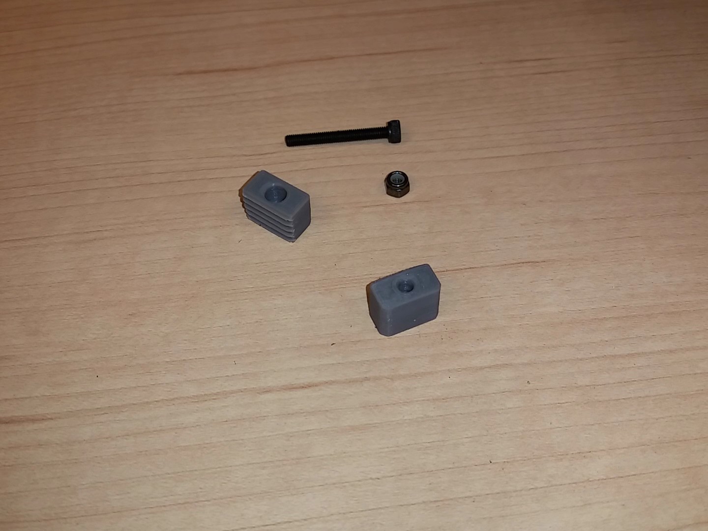 You will also need some fasteners for this project. You will need one 25mm M3 socket cap screw, two 16mm M3 socket cap screws, and three M3 Nylock nuts. You can use standard nuts, but we strongly recommend the use of Nylock nuts because they will not vibrate loose.
The first assembly step is to remove the existing hot-end, heather, thermistor, fans, and wiring from the stock X-Axis carriage. In these instructions the assembly instructions have been photographed with the complete X-Axis assembly removed from the printer for clarity, however, this upgrade can be done with the X-Axis installed in the printer with just the metal covers removed from the X-Axis and the Z-Axis gantry tower. The disassembly steps for the printer to get to this point have been omitted from this tutorial, because this is well documented in many other places, and is actually pretty obvious how to do anyhow.
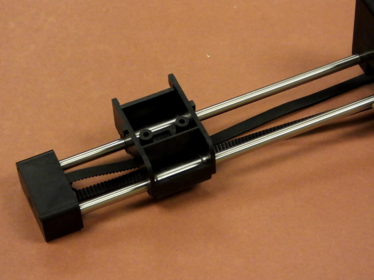
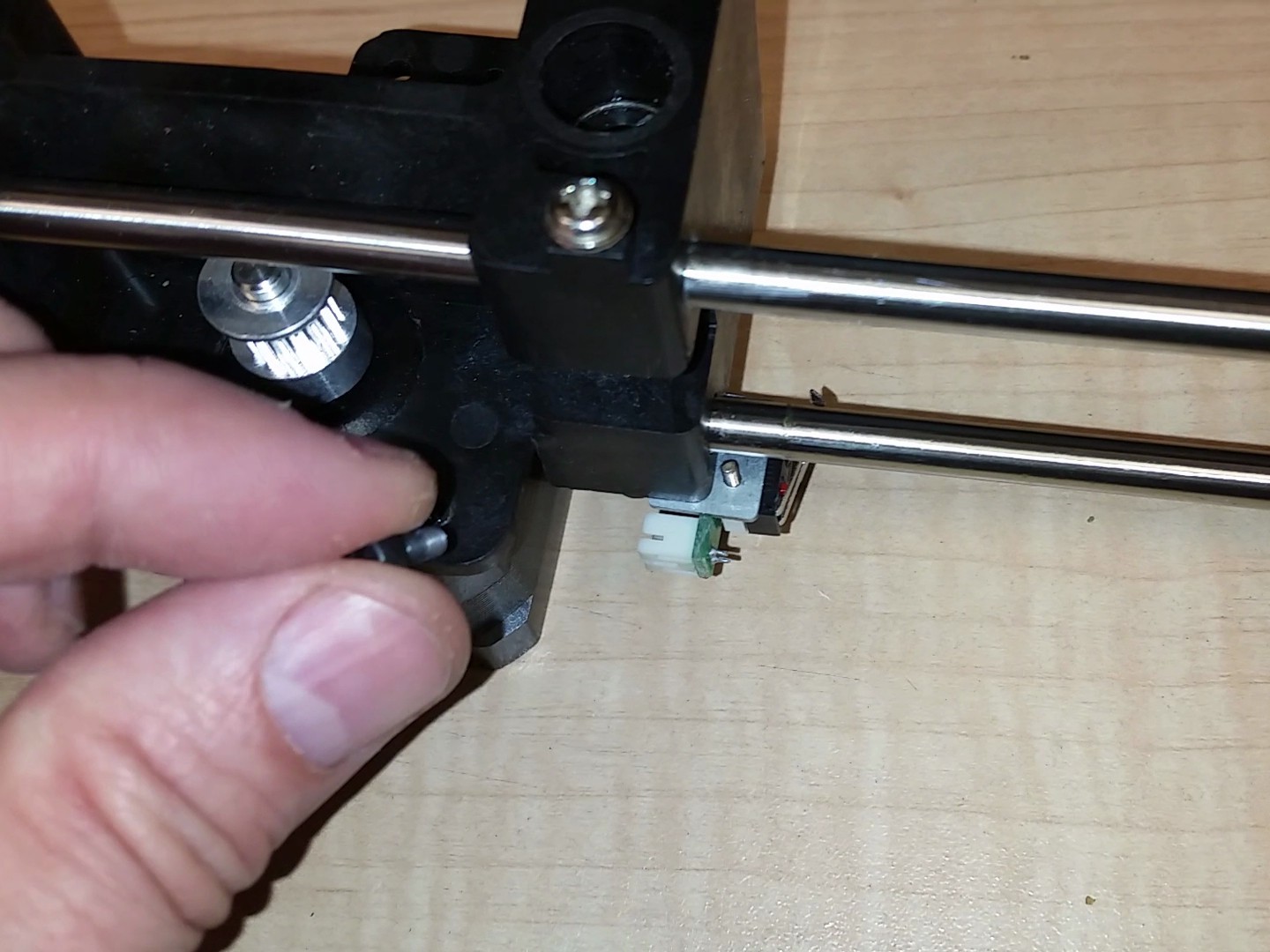
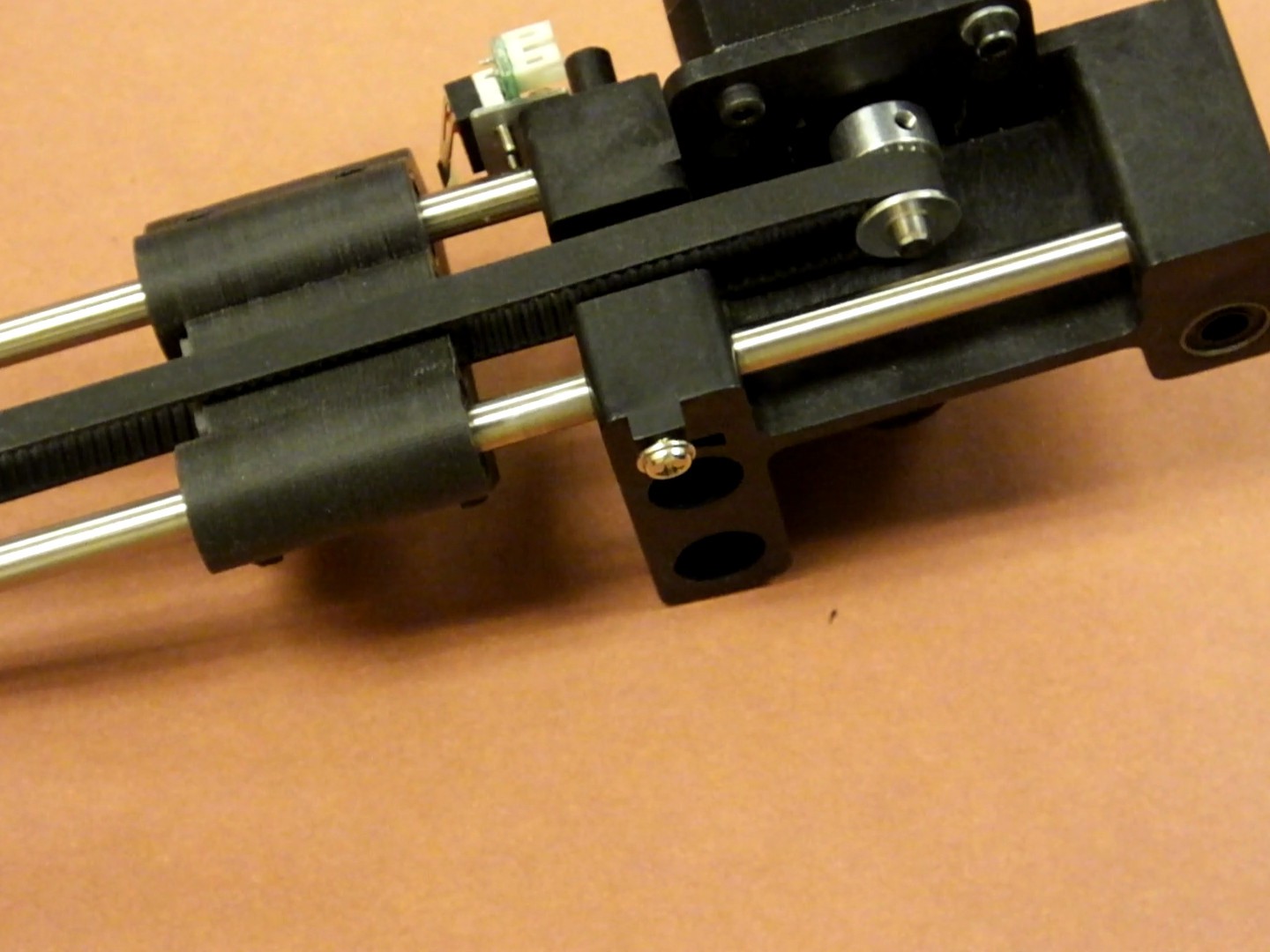
Remove the screw holding the X-Axis Pulley to the end of the X-Axis linear rods. Set this screw and pulley assembly aside for later. You will be reusing these parts.
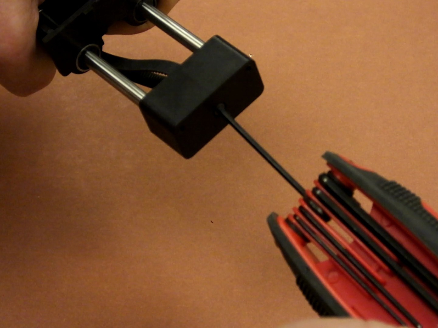
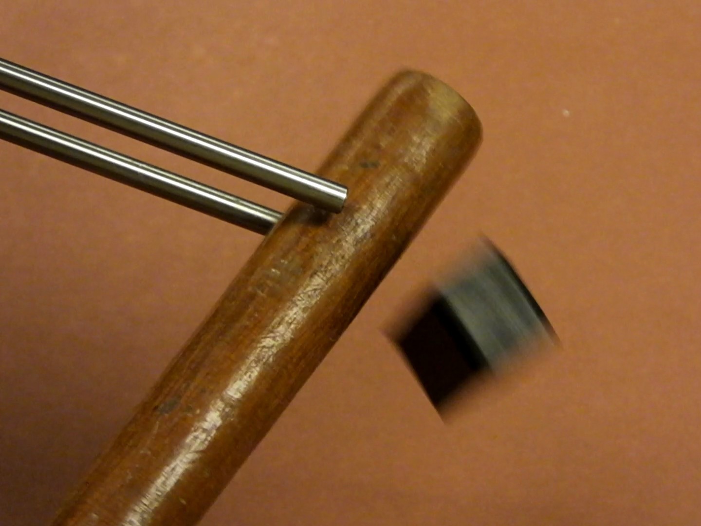 Gently tap on the inside of the plastic end cap for the X-Axis linear rods, until it pops off. It is just pressure fit on, and should come off relatively easily with a few sharp raps on the back side.
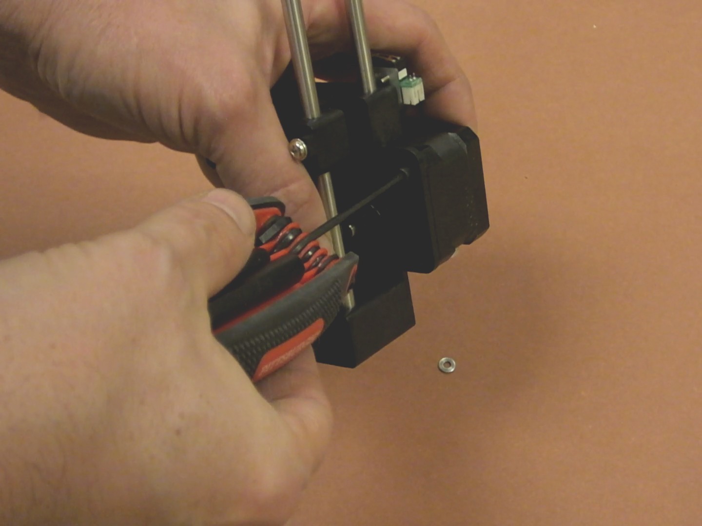
Remove the four M3 screws holding the X-Axis stepper motor to the gantry. Make a note of how your wiring is installed and routed, and also the orientation of the connector. You will need to note this so you can assemble it back the way it was originally installed. This seems to differ between different revisions of the printer.
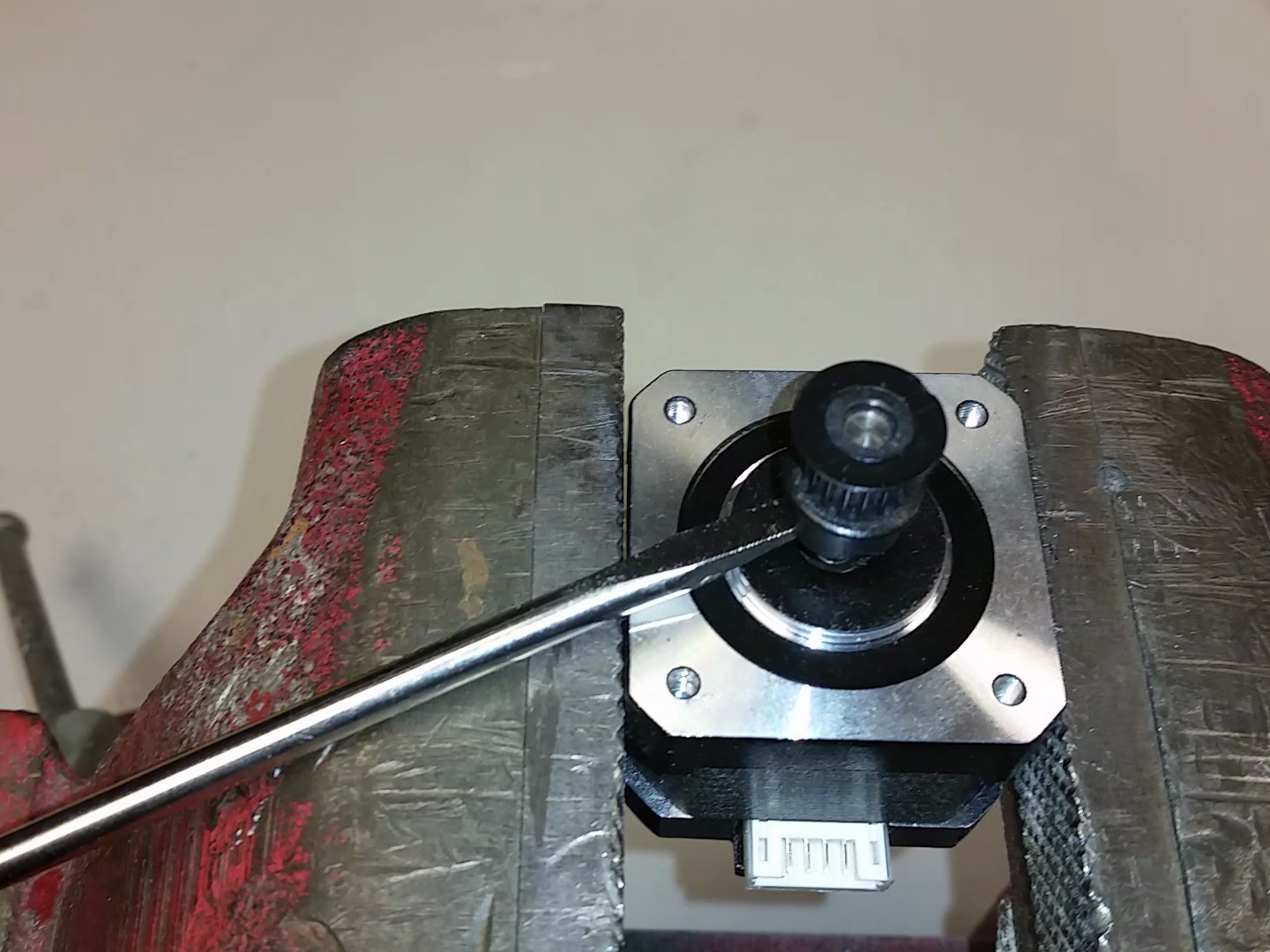 Pry the plastic toothed pulley from the end of the stepper motor shaft using a thin flat screwdriver or similar tool. The pulley is just friction fit over the motor shaft, so it will just slide off with some prying force. If the pulley is very difficult to remove, you can try warming the plastic pulley with a heat source and it will expand and soften and more easily come off.
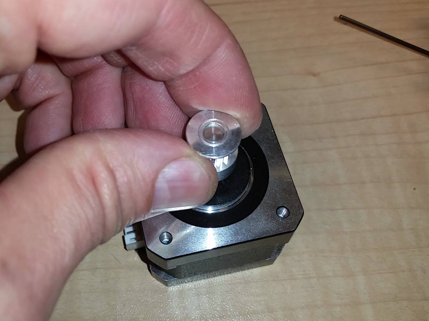
Install a new metal GT2 16T drive pulley on the stepper motor shaft. Don't fully tighten the grub screw because you will need to fine tune the height adjustment later.
Replace the stepper motor in the gantry and put the screws back in the same way they were when you removed the motor.
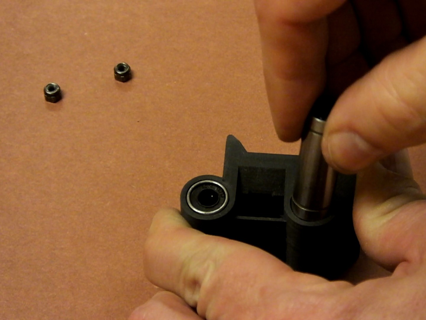
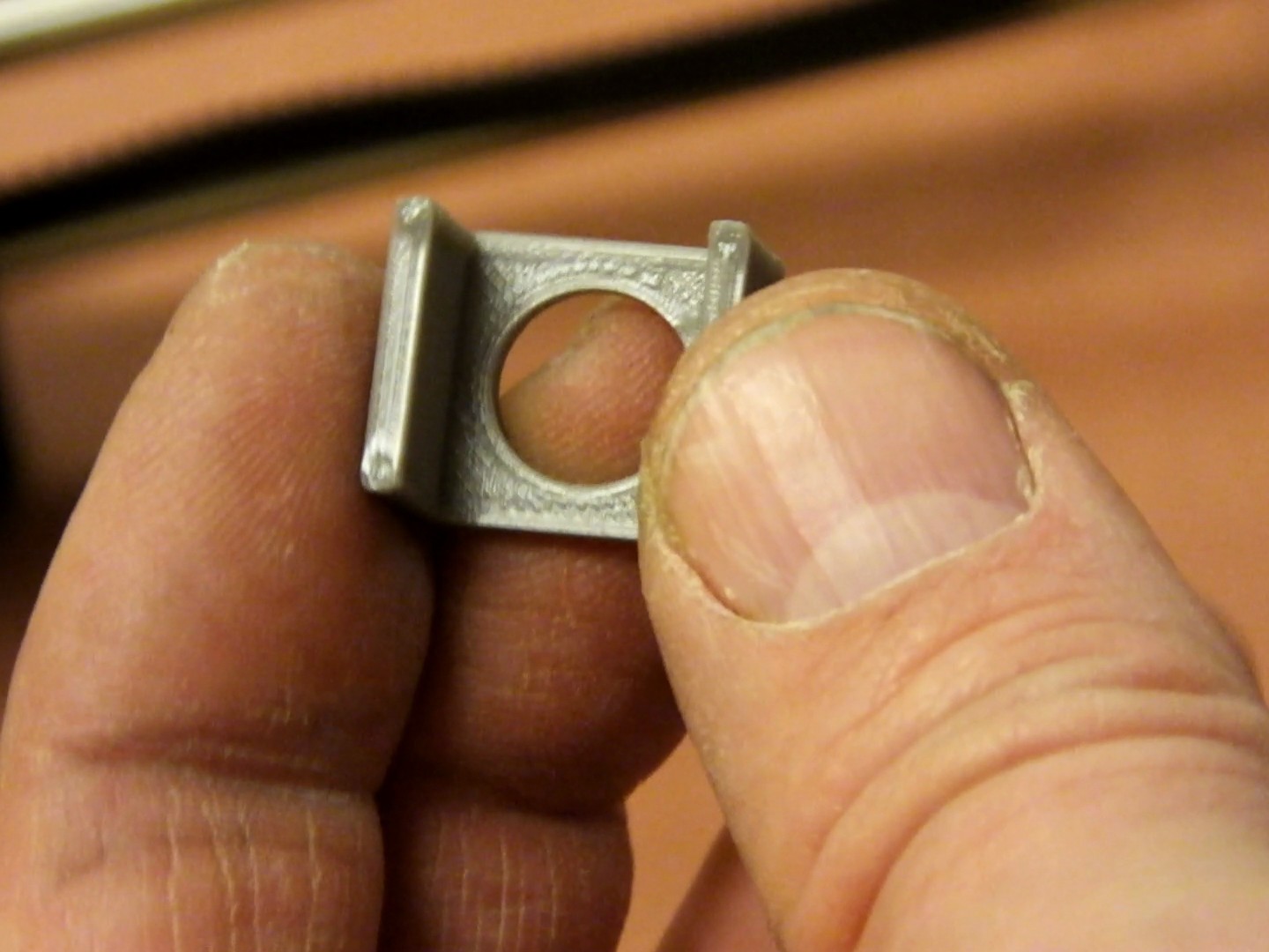
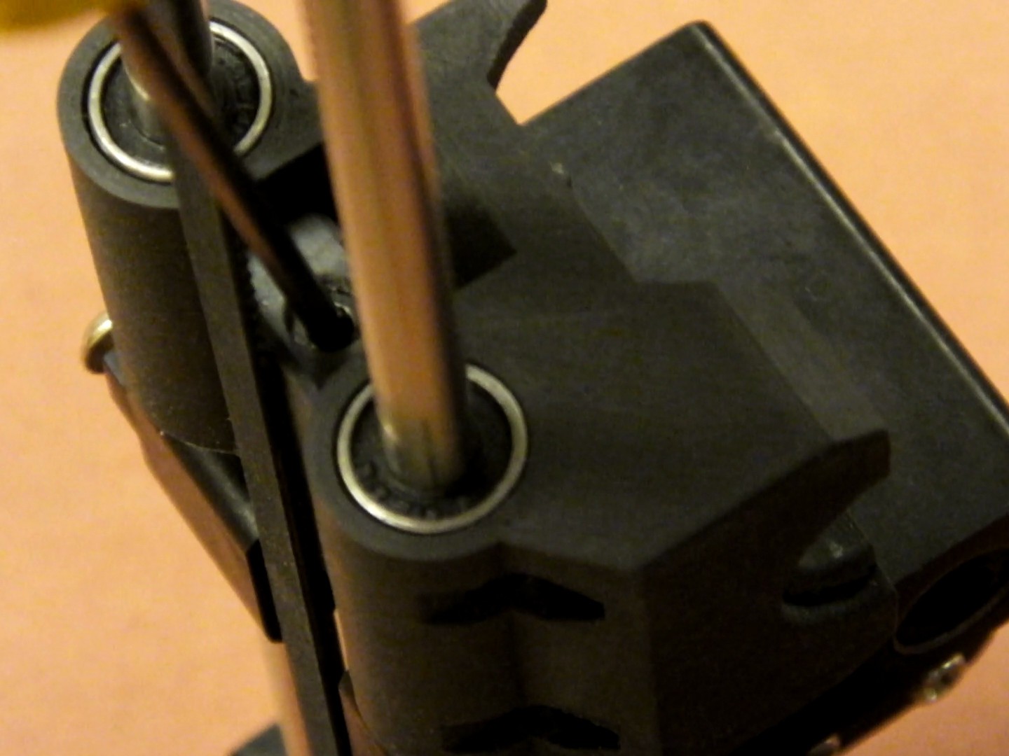
Insert the two LM6LUU bearings into the holes in the new X-Axis Carriage. The fit should be very snug. If you worry that the bearings may slip during use, you should put a little epoxy or CA glue on the side of the bearing before fully seating it.
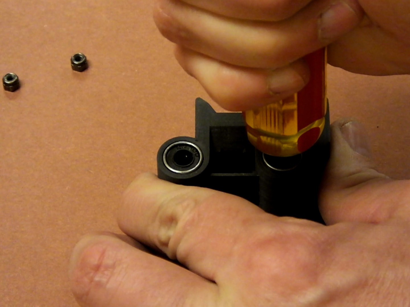
Press the bearings fully into the holes in the X-Axis Carriage. Do not hammer them or abuse them as you press them in.
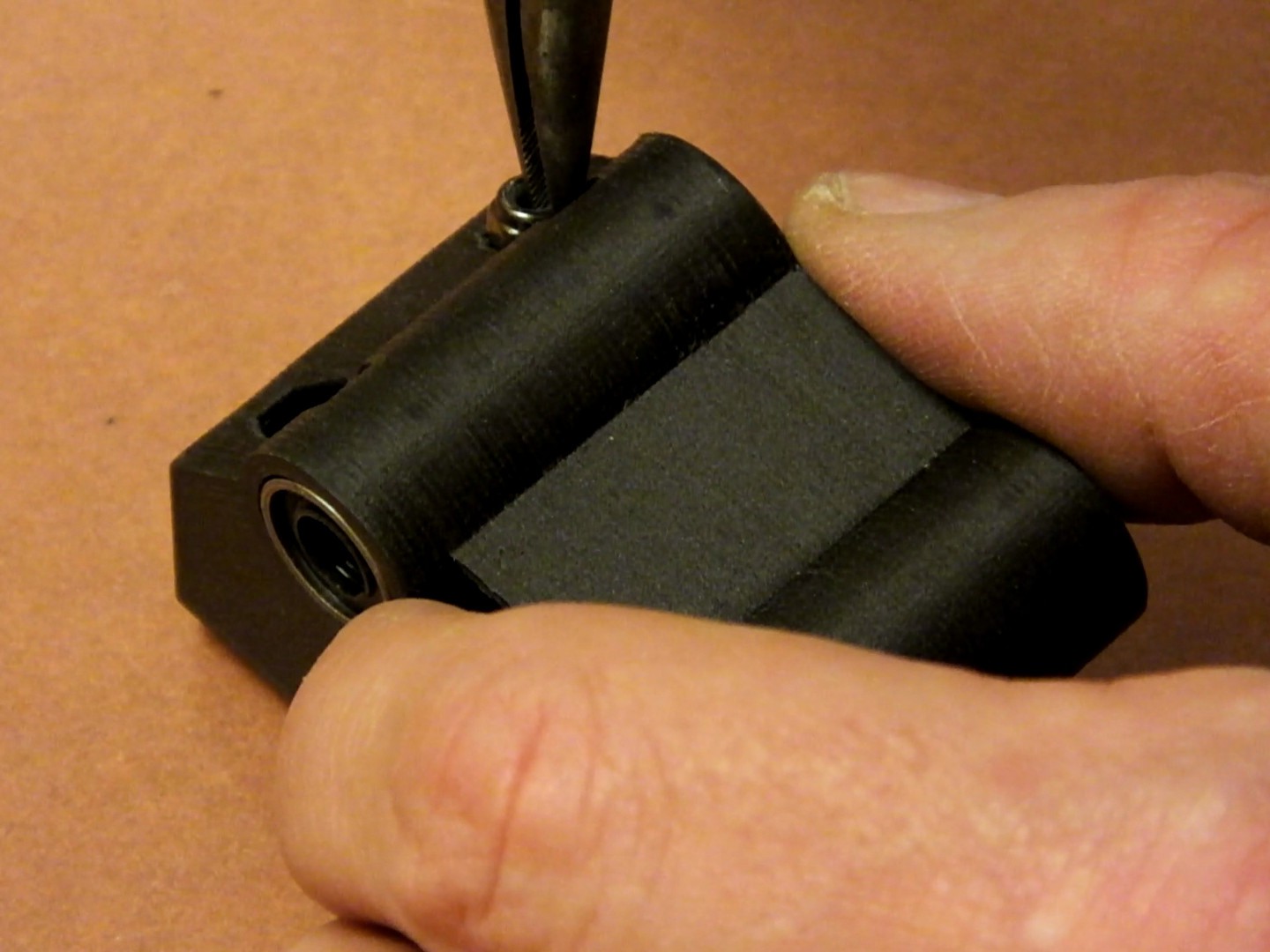
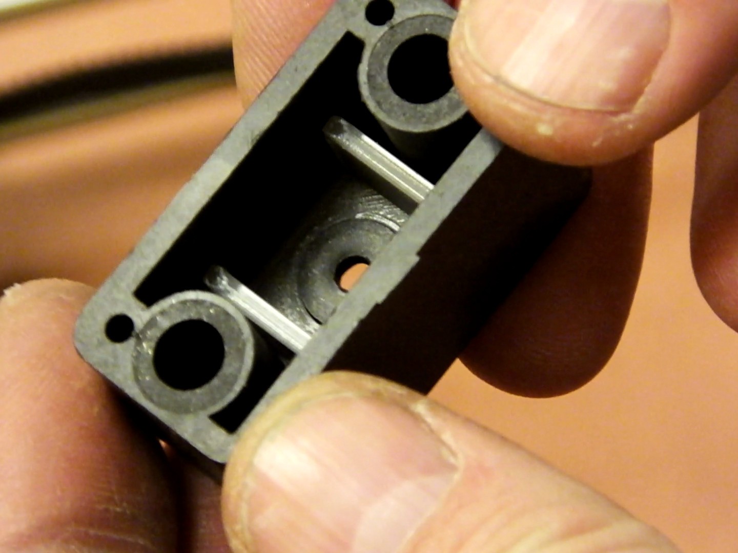
Insert two of the M3 Nylock nuts into the rear of the new Printed X-Axis Carriage. They should snap into place at the bottom of the holes.
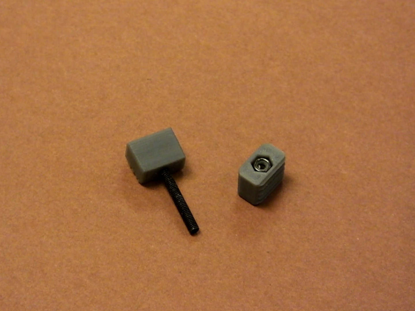
Insert an M3 Nylock nut and the 25mm M3 socket cap screw into the two halves of the GT2 Belt clamp, as shown here.
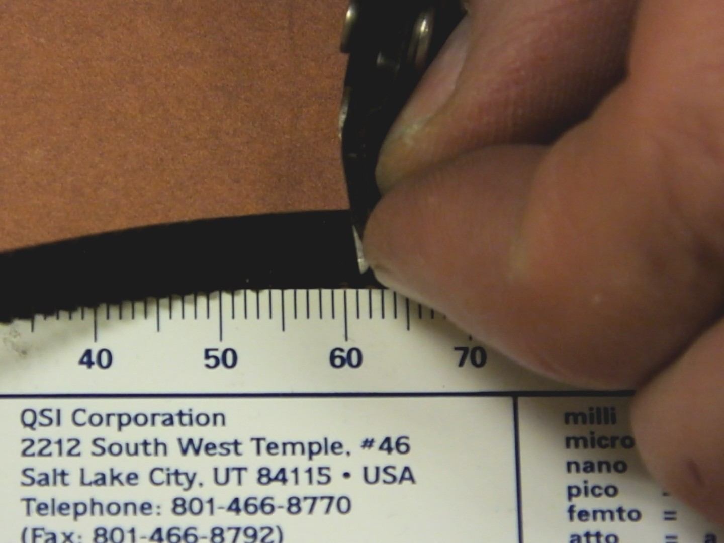
Cut a length of GT2 belt to 480mm (48cm). You can match the new belt to the one you took off to make sure you got the size correct, because the new belt will be the same size if you put them side by side.
Align the GT2 belt end with the GT2 clamp which has the 25mm M3 screw through it.

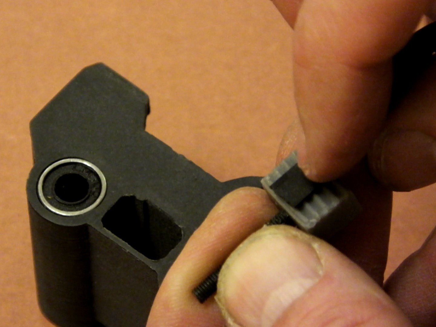
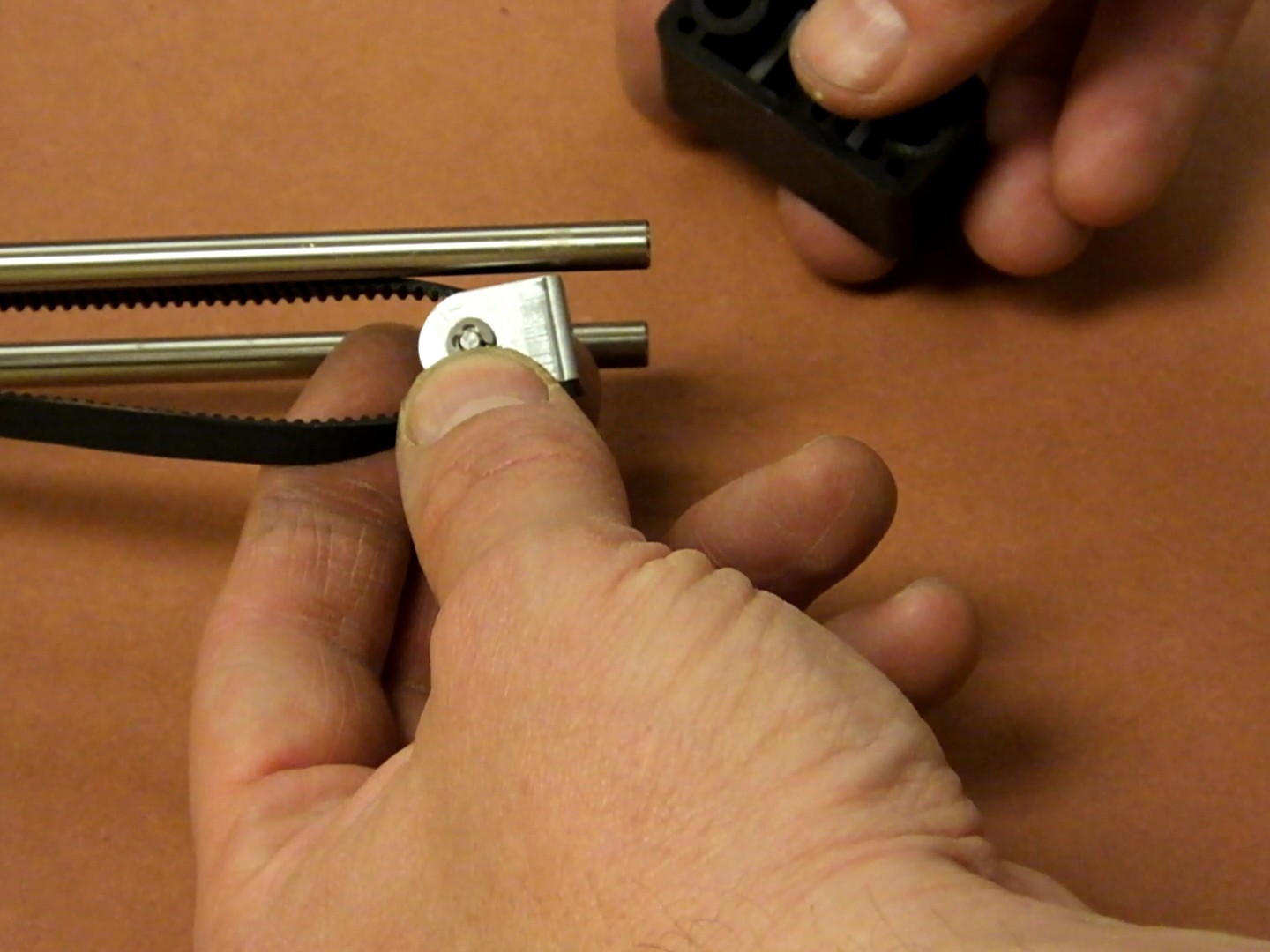
Insert the GT2 belt and clamp and screw into the right side of the new X-Axis Carriage. The teeth of the belt should face to the back of the carriage. The right side of the carriage has a more recessed hole for the clamp, the left side you will notice has no recess. Note: the recess allows for clearance of the idler pulley when then X-Axis is fully moved to the right, which gives another 3-5mm of X-Axis width to your printer.
Mate the GT2 clamp with the nut inside to the other end of the GT2 belt (make sure there are no twists in the belt) and insert this clamp and belt into the left side of the X-Axis carriage. Thread the screw of the right side GT2 clamp to the nut in the left side GT2 clamp at little bit, so the assembly does not fall apart while you continue to work.
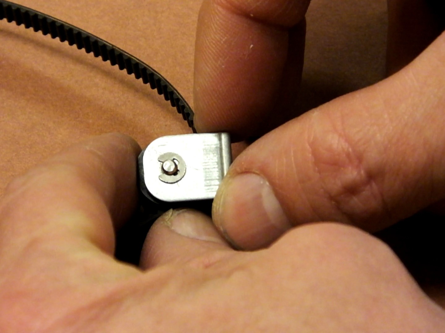
The original belt should still have the original pulley and bracket installed. You need to remove the C-clip that holds the pulley axle in place.
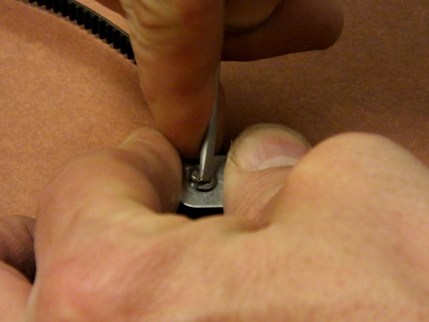
Slide the C-clip away from the axle as shown. Be careful it does not spring free and get lost.
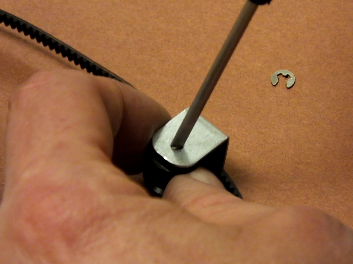
Slide the axle out of the bracket and remove the old belt and pulley.
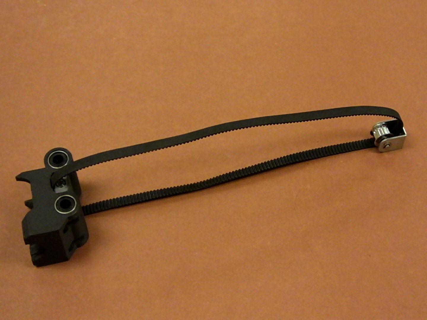
Insert the new GT2 belt through a new metal GT2 16T bearing idler pulley, and re-assemble this to the bracket and axle with the C-clip as shown here.
Install the optional pulley anti-rotation alignment clip, to make sure your pulley is perfectly aligned.
The pulley alignment piece fits into the end cap of the X-Axis before installing the pulley bracket, and prevents it from rotating.
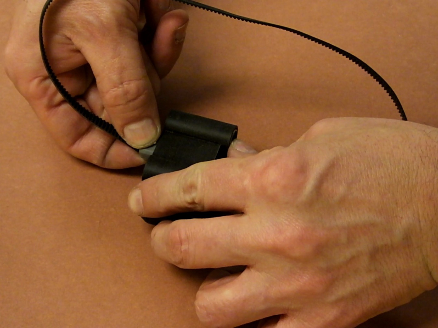
Slide the X-Axis Carriage over the linear rods and then make sure the belt is straight when the pulley bracket is inserted into the X-Axis end cap as you slide it on over the ends of the X-Axis linear rods.
Replace the screw holding the pulley bracket in place and tighten the screw. Tap the end of the plastic X-Axis end cap to fully seat it on the ends of the linear rods. Make sure the new GT2 belt is looped around the new GT2 drive pulley on the stepper motor.
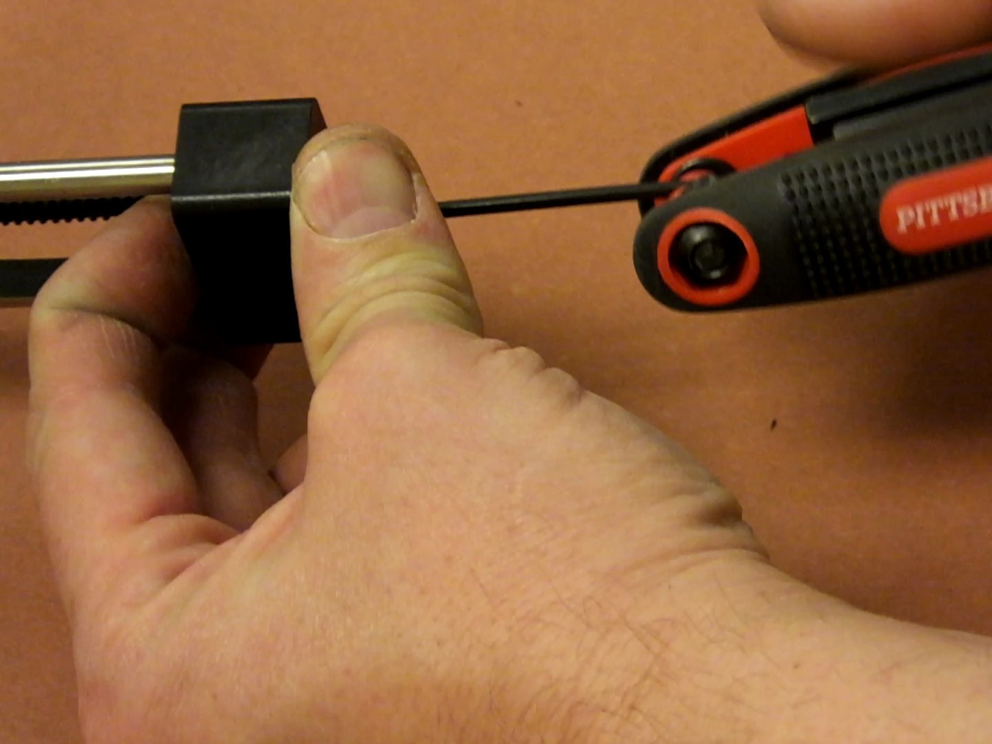
Loosen the grub screw on the stepper motor pulley, and fine tune the alignment of the pulley with the path that the belt takes. You want the belt to be perfectly straight and parallel. Then tighten the grub screw holding the pulley to the stepper motor.
Tighten the 25mm GT2 clamp screw to tension the new belt to your liking. It should be taught, but not so much that it becomes difficult to slide by hand.

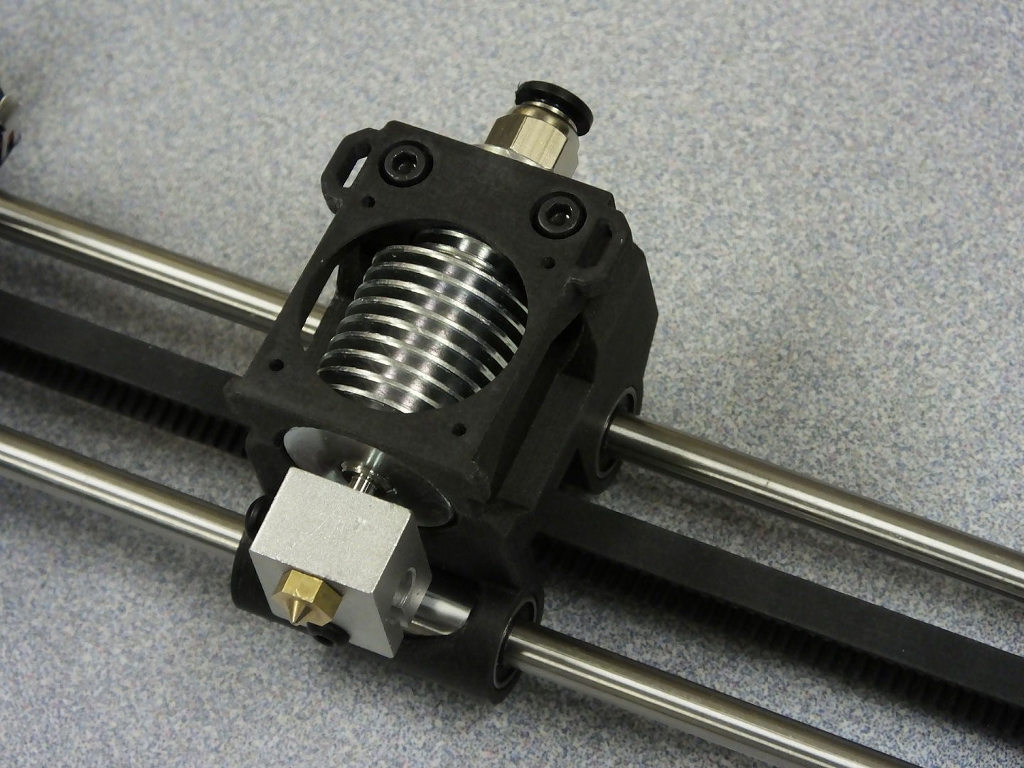
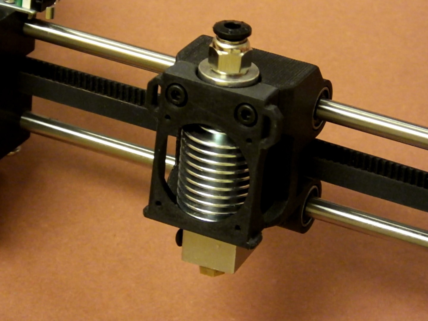
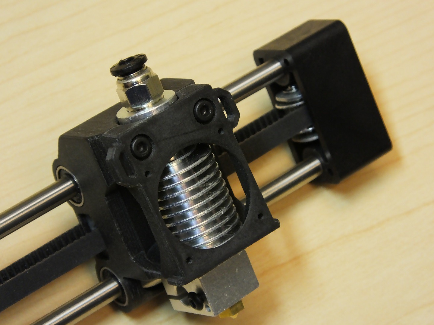
Install an E3Dv6 style hot end into the new X-Axis Carriage.

Two 16mm M3 socket cap screws secure the printed clamp/fan bracket to the new carriage.
You're ready to install the wiring back on the new hot-end and reassemble any parts of the printer you removed to get access to the gantry.
At this point, you should be ready to configure the main board with the new GT2 belt drive parameters.
Calibrating the printer CPU for the new GT2 X-Axis belt and pulleys is simple, and you must do this or the size of your prints will be wrong. You can use the calculator at www.prusaprinters.org/calculator to find out the correct steps per millimeter for my motor and lead screw combination. The X-Axis in the MPSM V1 is a 1.8 degree (200 steps per revolution) motor, and the printer can do 1/16th microstepping. The GT2 belt is 2mm Pitch and the pulley is 16 teeth.
Plugging those numbers into the calculator gives me a result of 100 steps per millimeter. The calculator even nicely reminds you that the G-code for this uses the M92 command. For the V2 the motors do 1/8th microstepping, so the result value is 50 steps per mm, so adjust the settings below accordingly.
All that's left to do is send this to the printer to tell it the new value for X steps per mm and we're done. The easiest way to make this happen is to open up a text editor and create a text file and stuff the commands into it and then save it as "xxxx.gcode" and take it to the printer and print "xxxx.gcode" (use any name you like in place of xxxx.gcode). The printer will read the settings and configure the printer accordingly. The extra commands in this print file are there to make the printer home the axis so you get some feedback that the file printed, and the motors turn off at the end so that you can move them axis by hand once the configuration is finished.
The file looks like this for the V1:
M92 X100 ; Configure X Motor M500 ; Save New Settings
G28 ; Home All Axis
M84 ; Disable All Motors
Enjoy your new carriage, and stay tuned for a similar fix for the Y-Axis!
Discussions
Become a Hackaday.io Member
Create an account to leave a comment. Already have an account? Log In.
Use a blow torch to remove the black plastic from the stainless steel x rods. No amount of pulling or smashing would loosen them until I heated the steel considerably. Besides, pulling them just translates to bending the z rails or damaging something else.
Are you sure? yes | no
Nice, would you mind sharing your cad files step iges or preferably fusion 360 format.
Kind regards/Stefan
Are you sure? yes | no
Great Post. Do you know the length of the LM6U bearings? I see 19mm length on Amazon but would like to confirm.
Are you sure? yes | no
Just finished this upgrade and so glad I did it! I have a Mini V2 bought at Christmas 2017 and have a few notes from my experience. The plastic cap on the end of my x-axis was glued on and I had to really heat and hammer it to get it off. It's a bit deformed now, but luckily still went back on. The small printed x-axis belt tensioners needed quite a bit of sanding to get them to fit properly as well. The idler pulley on my x-axis had a riveted pin which needed replaced when reinstalling.
Are you sure? yes | no
Glad to see a recent post on this, question. Where did you get your idler? I was able to find the drive shaft on Amazon, but the idler seems tricky to track down on Ali or elsewhere. Or did you reuse what you had?
Could use the help that's the only component I'm missing to put this printer back together, appreciate it!
Are you sure? yes | no
These should work (AMZ): WINSINN GT2 Idler Pulley 16 Teeth 3mm Bore 6mm Width Timing Pulley Wheel Aluminum for 3D Printer (Pack of 5Pcs)
Are you sure? yes | no
Quick question thats been rattling around in my head. with the weight of the hot end, fan(s) shroud etc all to the front of the printer would print quality improve if we "balanced" the hot end carriage? I'd like to print this for my V2 but place the filment cooling fan and shroud behind the gantry. Does this make sense?
Are you sure? yes | no
You can add Superglue Debonder to the required tools list - I found that the X gantry end cap was glued to the rods.
Are you sure? yes | no
I took a picture of the ruler so I wouldn't have to write the number down, and I believe I placed the belt on the wrong side of the ruler and didn't notice. I have to re-measure it if nobody else figures out the right length before I get home and find the ruler I used. Sorry!
Are you sure? yes | no
Haha no worries. Figured maybe it was just a typo. Ended up order a big spool of 6mm GT2, figure between another printer I'm working on and the possibility of pulling the trigger on going to a bigger bed for this I may as well. Getting to the point where there's not much Monoprice left on my printer :)
Are you sure? yes | no
I feel ya on that one. I've done these last two mods, and I have parts on order to swap out the main board for an Arduino Mega/Ramps setup. I want to put in a PT100, and the original motherboard just doesn't have the pins needed.
Are you sure? yes | no
Finally got this all assembled, nice work. Belt ended up being about 475mm for me, just a little check/recut during assembly to get it just right.
Can't say I'm thrilled with the noise I'm getting from the bearings I ordered off Amazon. Quite a bit louder on an x-movements and seem to translate the vibrations from the fan through to the rest of the printer.
Had issues with the internal hex locks for the clamp/fan mount. Ended up using some 10mm standoffs to make a coupling that could grip in the channel (which was a tighter fit for me). Not a huge deal and had the side benefit of giving me a mounting point for a rear mount parts fan that I'm slowly working on.
Are you sure? yes | no
Is 60mm the correct length for the belt?
Are you sure? yes | no
he updated the comment on the photo its 48cm
Are you sure? yes | no