 Emerica
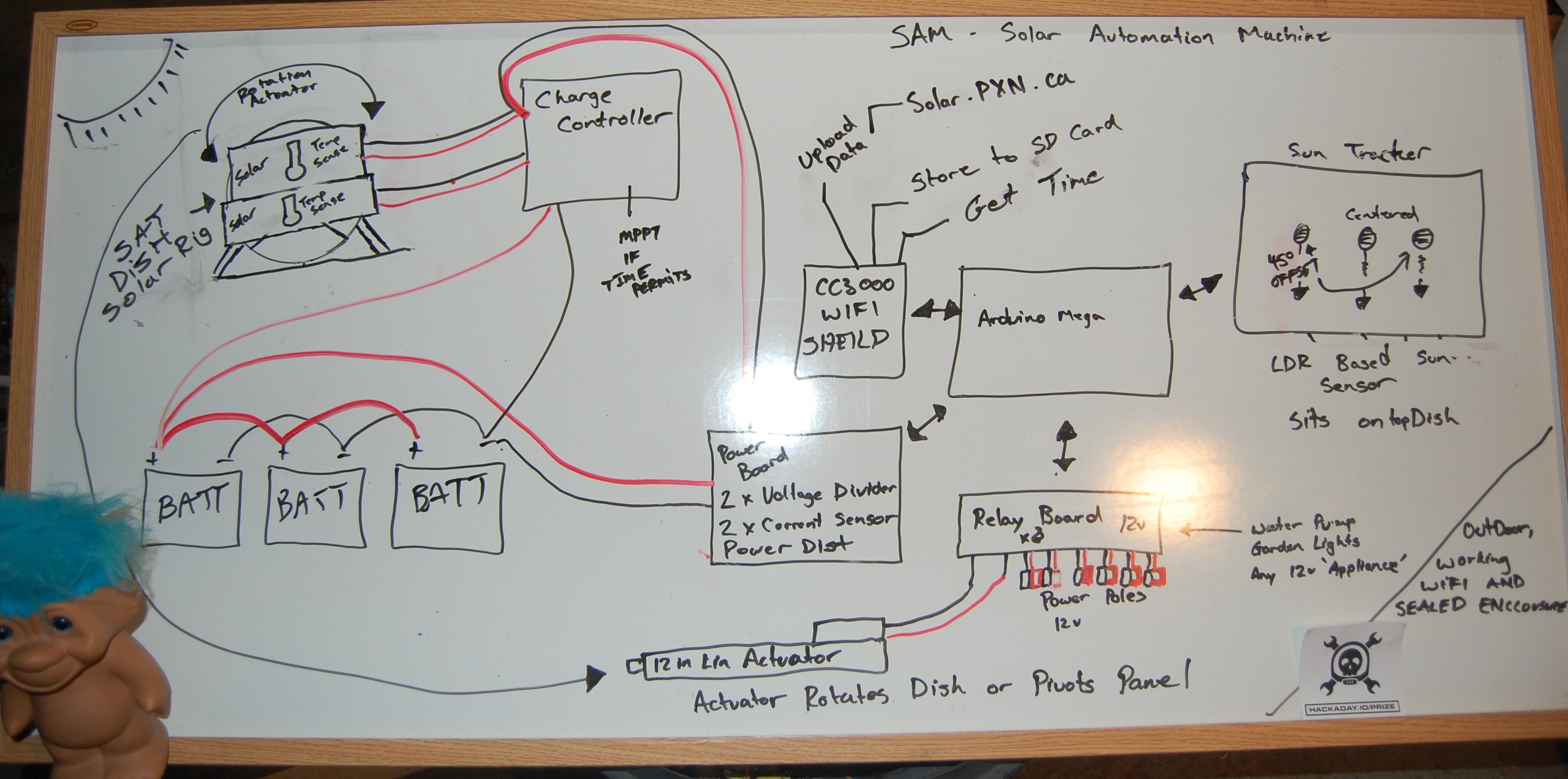
Sam is to be a smart solar charge monitor and controller with extras.
SAM will:
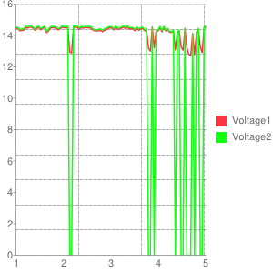
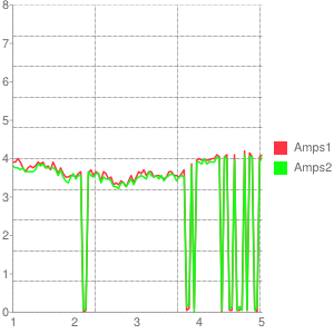
-monitor the voltage and current on my solar panels
-monitor the voltage and current on my batteries
-monitor the temperature of the panels and system
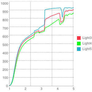
-monitor the light levels of the sun
-move the panels to stay in the sun
-charge the battery with an arduino mppt charger if time permits.
-turn on devices like garden lights, water pumps, lawn ornaments, or even model rockets.
-Store all the sensor data to sd card
-Upload data sets to solar.pxn.ca via wifi.
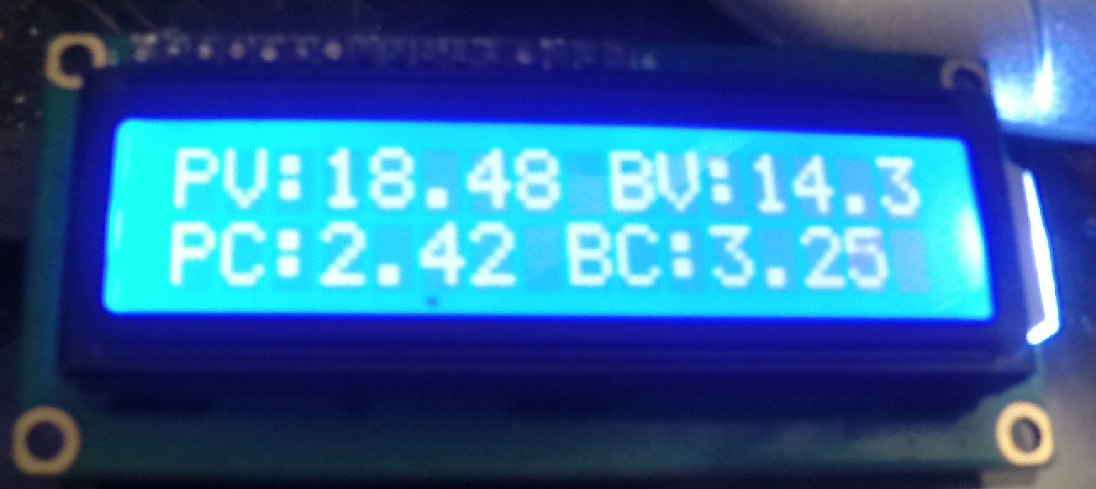
-Display the current status on an lcd
Where am I at today:
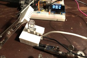
Much of the rough hardware is now completed, I need to put it all together and finish work on the software.
SAM consists of:
- Arduino Mega
- cc3000 wifi shield
- 12V 8x Relay board
- Sunforce Charge Controller
- Voltage & Current sensors
- Temp Sensors
- Alarm
- Lcd Display
- Solar panels and batteries
- Linear actuator
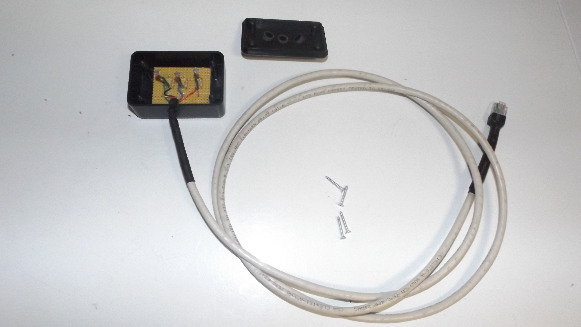
- Sun tracker module
What code can be open sourced will be open sourced as it becomes polished.
The current online instance at http://solar.pxn.ca is just for testing/proof of concept, (though is mostly functional)
Arduino libraries will be used for wifi c30000 , lcd display and possible more.
A database abstraction library might be used on the web side to ease database interaction.
More will be known about the software license compatibility as it's developed.

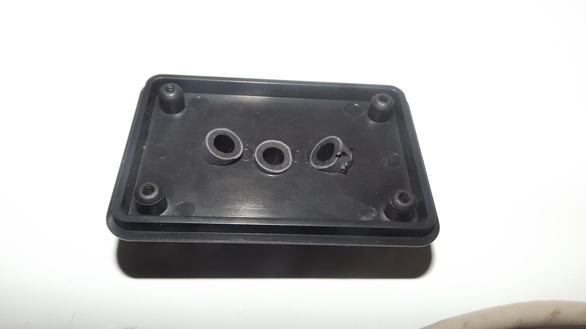
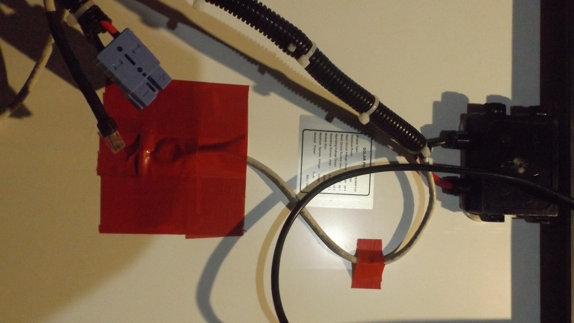 The small strip to hold it while I got the rest of the tape down.
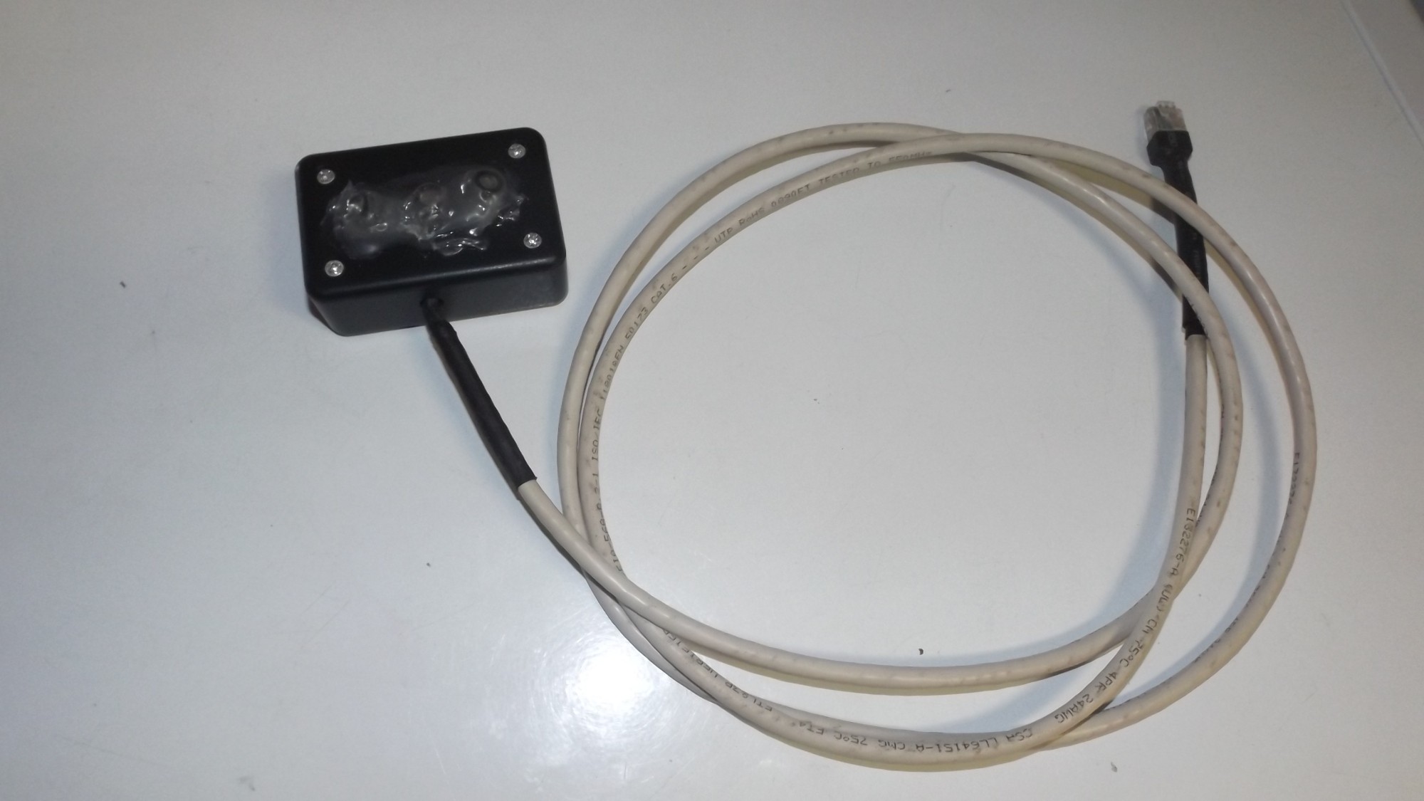


 Kody Alan Rogers
 albert
 Open Green Energy
The SAM (Solar Automation Machine) is an innovative solution designed to automate and streamline solar panel installation processes. Developed with advanced technology and precision engineering, SAM revolutionizes the efficiency and accuracy of solar panel installations.
Moreover, SAM incorporates advanced connectivity and control systems, allowing for seamless integration with other components of a solar power system. It can be integrated with monitoring and management systems to provide real-time data on energy production and system performance.
With Worios, a state-of-the-art technology designed to enhance performance and efficiency, SAM utilizes advanced energy management and optimization techniques. This ensures that the solar power system operates at its highest efficiency levels, maximizing energy production and minimizing losses<a href="https://worios.com/">Worios</a>