Kenji Larsen
I classify this as a material Processor because it converts hot water to less hot water. There are sensors, which means it is also a (data) Collector, as per general Reactron node categories, but it has an active actuator, the fan, which allows for enabling and varying heat exchange operations. It may be simple as processors go, but the heat extraction is in fact a controllable process, within certain ranges.
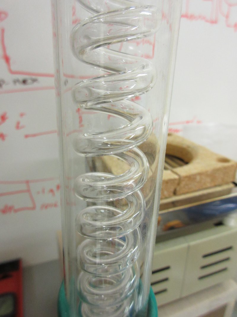
Fifty feet of quarter-inch copper tubing was wound into three coils of different diameters, 2.375 inches, 3.5 inches, and 4.5 inches.
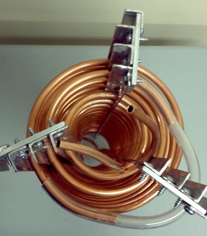
Each coil has sixteen loops. The coils were wound around standard PVC pipe of those diameters. The coils were then threaded into aluminum L-channel with evenly spaced holes to determine the coil spacing. The three coils were then nested and secured together as a unit.
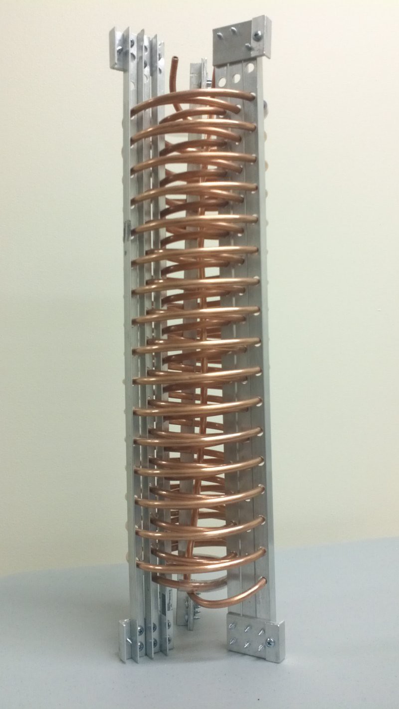
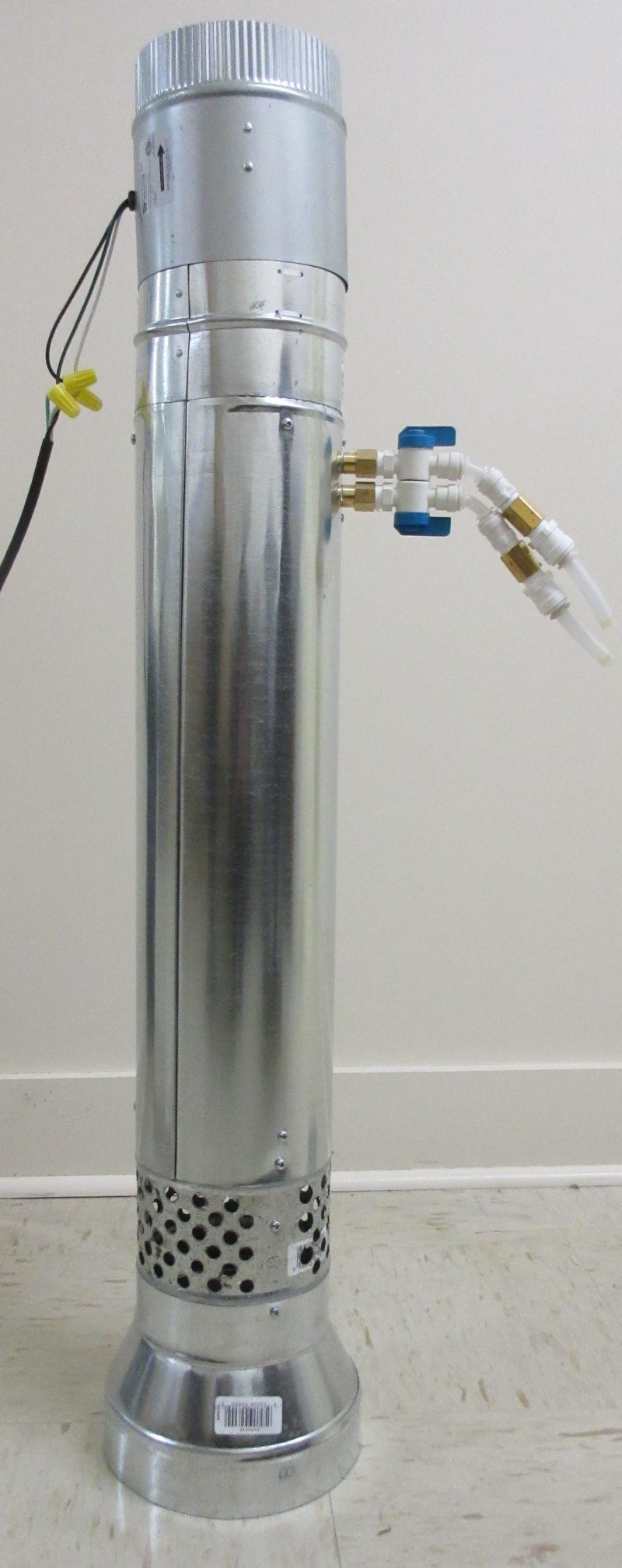
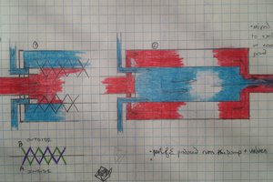
The individual coils are connected via vinyl tubing, goes through a matrix of valves to allow parallel or series flow through the coils. Series flow through the coils results in a low flow rate, due to higher friction loss.
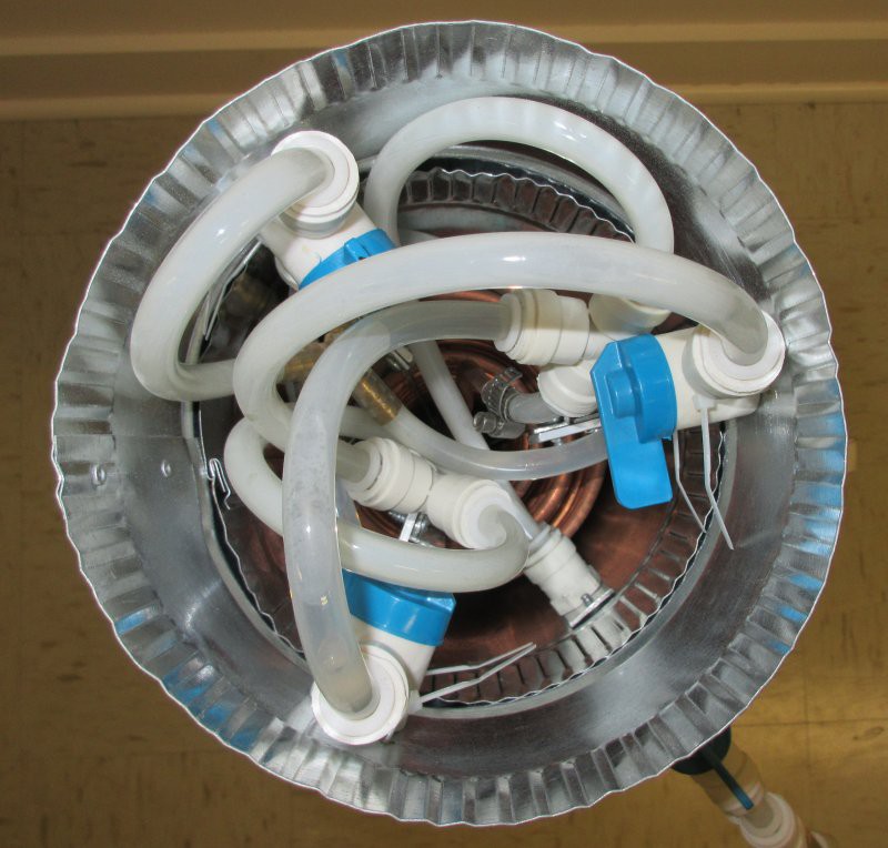
This can actually be a benefit, since a reduced flow rate means that a fluid may spend more time in the exchanger, resulting in lower output temperatures. If a larger flow rate is necessary for a process, parallel flow may be selected, for higher rates, at the expense of higher outlet temperature. A similar amount of heat is extracted from the fluid (there is some difference due to thermal efficiency gains).
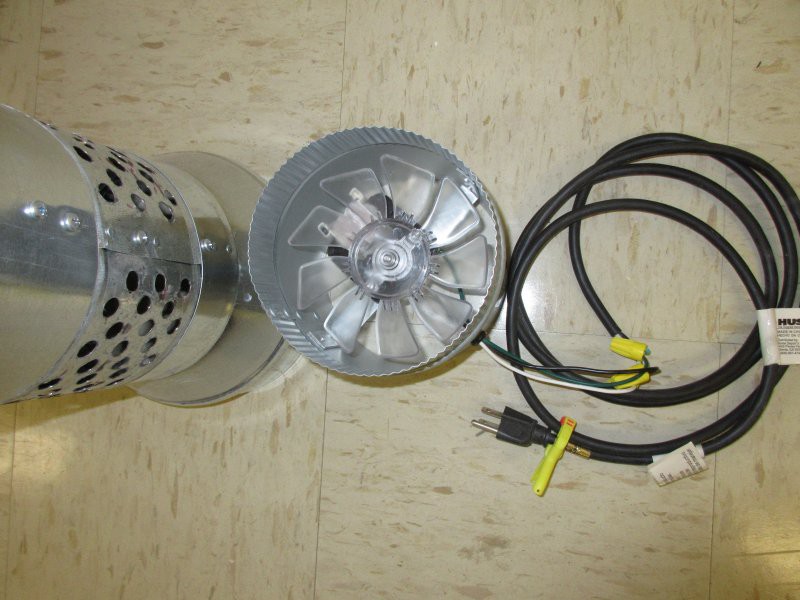
The triple nested coil unit was secured inside a standard, inexpensive six-inch ventilation duct. This allowed for the usage of a standard six inch duct fan for the air flow generation.
An eight-inch to six-inch adapter acts as a stable base and is drilled with holes to allow for air input at the bottom of the column, where air will be coldest.
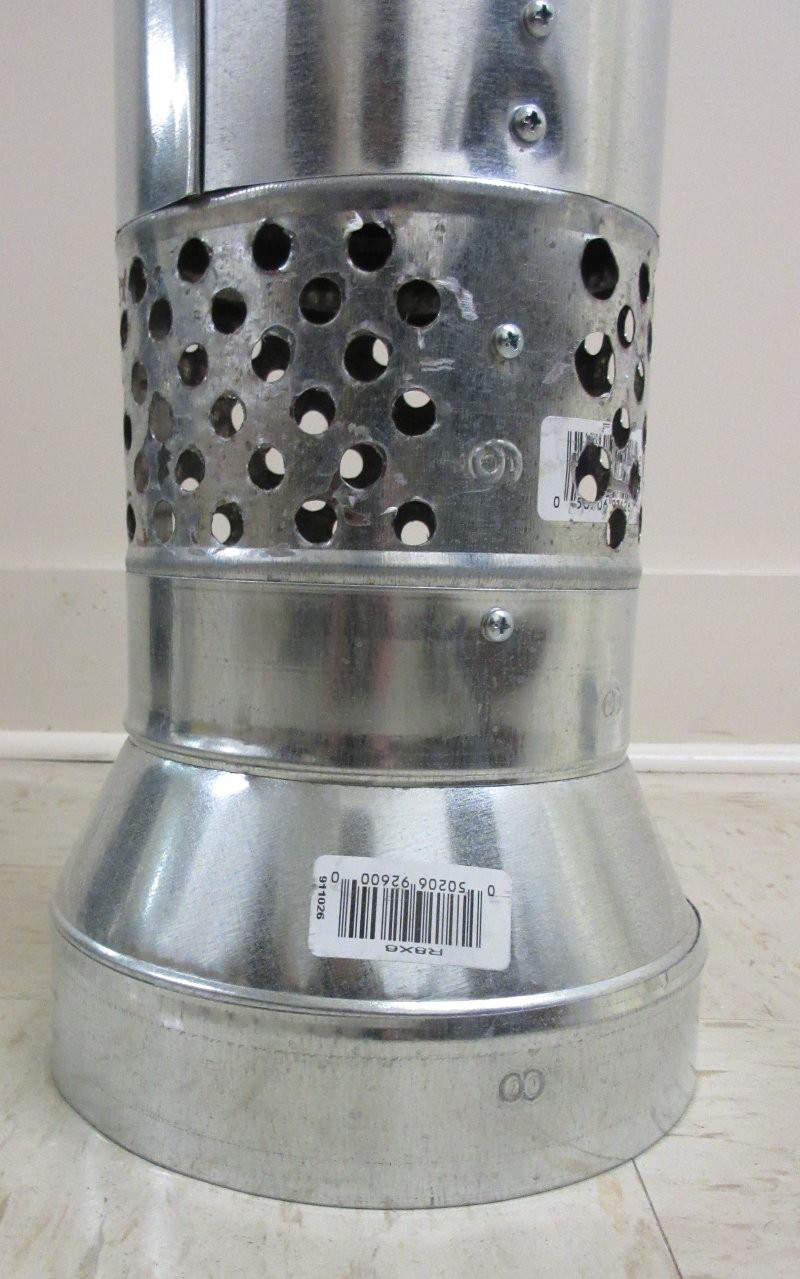
Heated air is expelled out the top. The vertical configuration of the exchanger means it has a very small footprint.
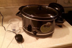
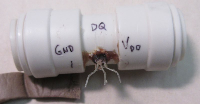
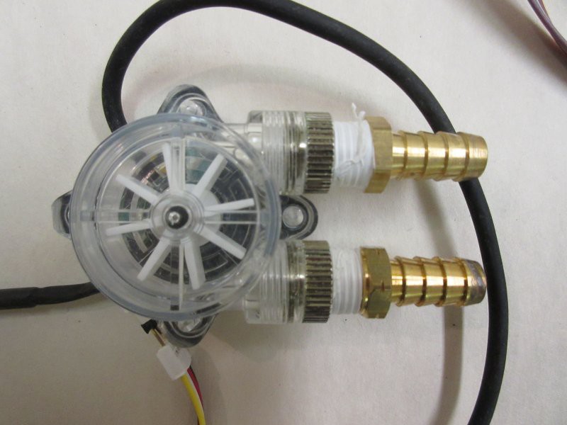
Dallas DS18B20 sensors are situated at top and bottom, near the center of the duct, where the fastest air velocity is expected. The water inlet and outlet are similarly monitored, with fittings just external to the ductwork. These fittings are usually covered by foam insulation, so that the ambient air does not cool off the sensors from the back. The fittings were drilled and the sensors epoxied in, such that the packaging is in direct contact with the water. A flow rate sensor is also in line.
All sensors are monitored by an Arduino clone attached to a HopeRF transceiver, and may be used by the Reactron network as parameters. Specifically, when this is tied to a water distiller, the water loop is the coolant in a Graham condenser.
This extracts heat from steam. The distiller can put more heat in than the exchanger can take out, per unit time, so the temperature of the cooling water rises. The water pump is an inexpensive aquarium pump that is not rated for more than 36 degrees Celsius, and is the component in the loop with the lowest rating. The pump is located in a reservoir that is tied to the outlet of the exchanger. Generally the reservoir has a slightly lower temperature than the exchanger outlet, so it is sufficient to monitor the exchanger outlet temperature and command an Energizer to deactivate the electric heat source from the boiling flask, when it hits a threshold temperature. Once a low enough temperature is achieved, heat input may be resumed automatically. Human intervention is not required.
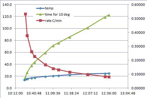
The following graphs were created by other requesting nodes on the Reactron network, each interested in a different interpretation or consequence of the various data. Those nodes work only their task of calculation and data recording and visualization, without any interaction with the heat exchange process, other than requesting the data. The exchanger is also focused only on its one task - to remove heat from the fluid.

 ken.do
 Simon
Simon
 Tim Rightnour