 Nelson Phillips
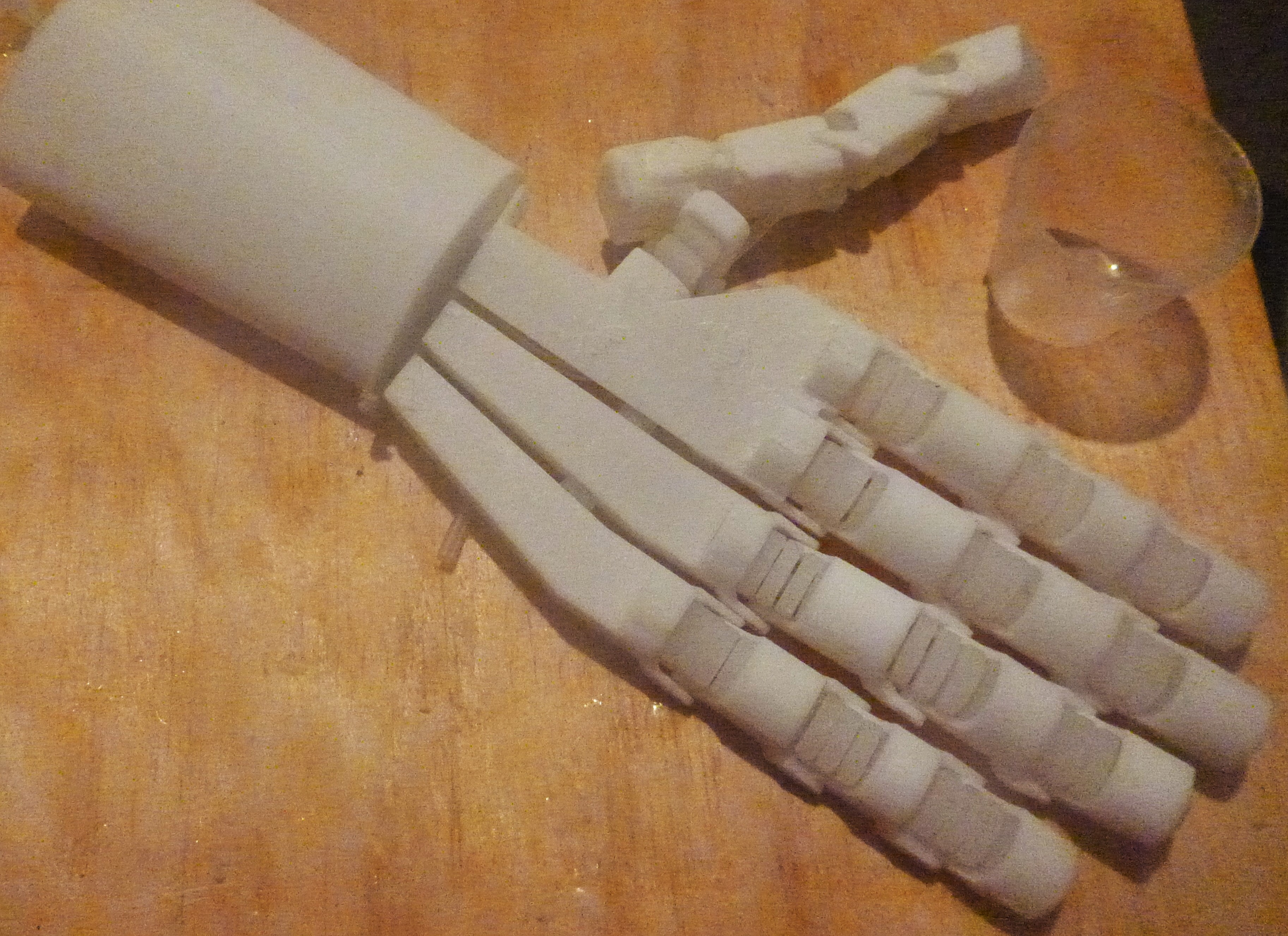
The aim of this project is to create a prosthetic hand that would be more appealing to a teenager as opposed to the many opensource hands available to the under 12's. Thus the difference is mostly aesthetic in form and function, that is more relational and nuanced.
For a prosthetic hand to aid function and a humanoid robot to function as you would expect it to the artificial hand must not only be similarly functional but have an appearance of handness. Hands that function as social objects as much as environmental manipulators. Gesturing, high-fiving and handshaking require handiness to perform such communicative roles. So it is with this emphasis that as well as a environmental manipulator this project aims to create a more sociable hand.
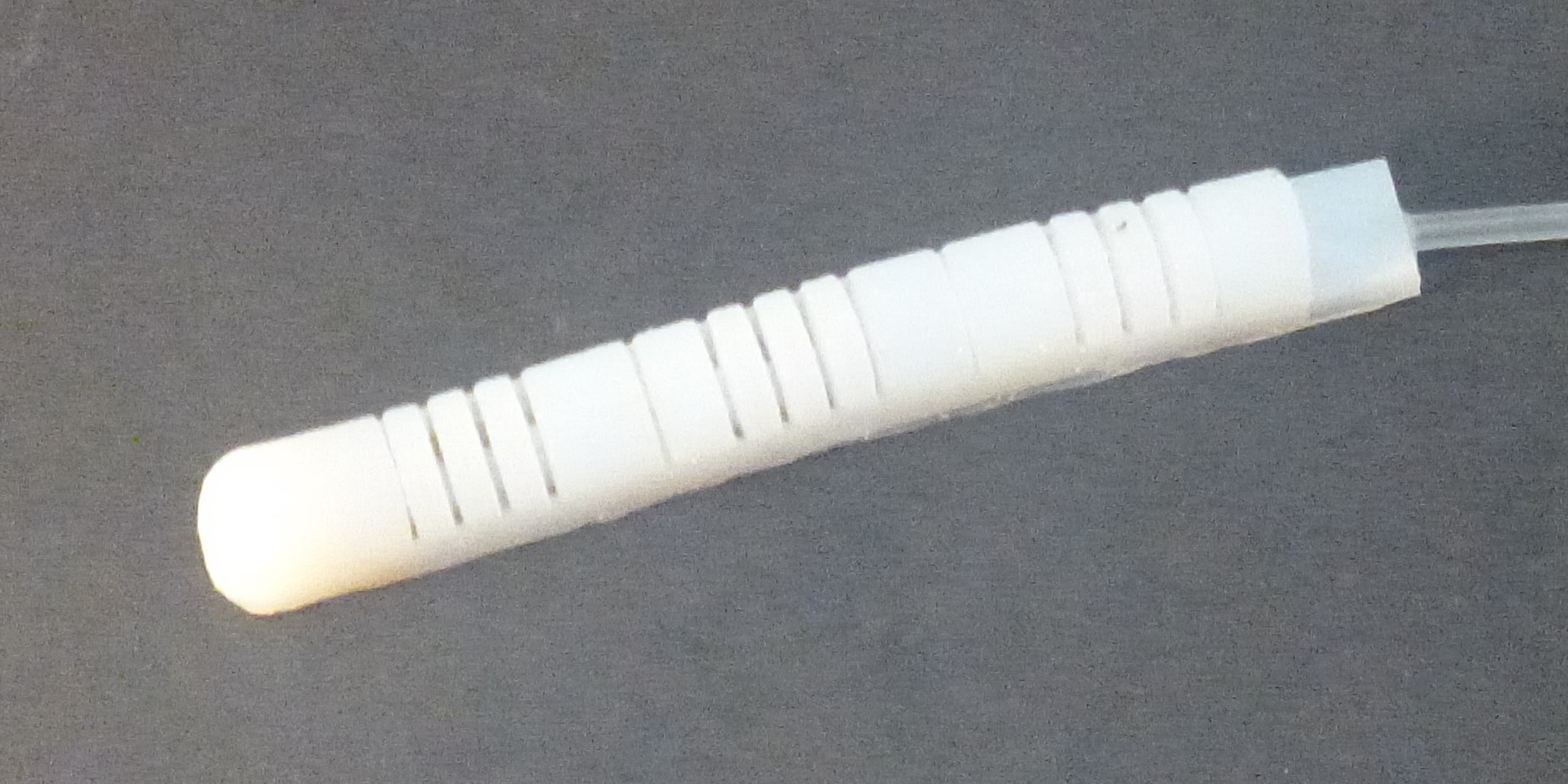
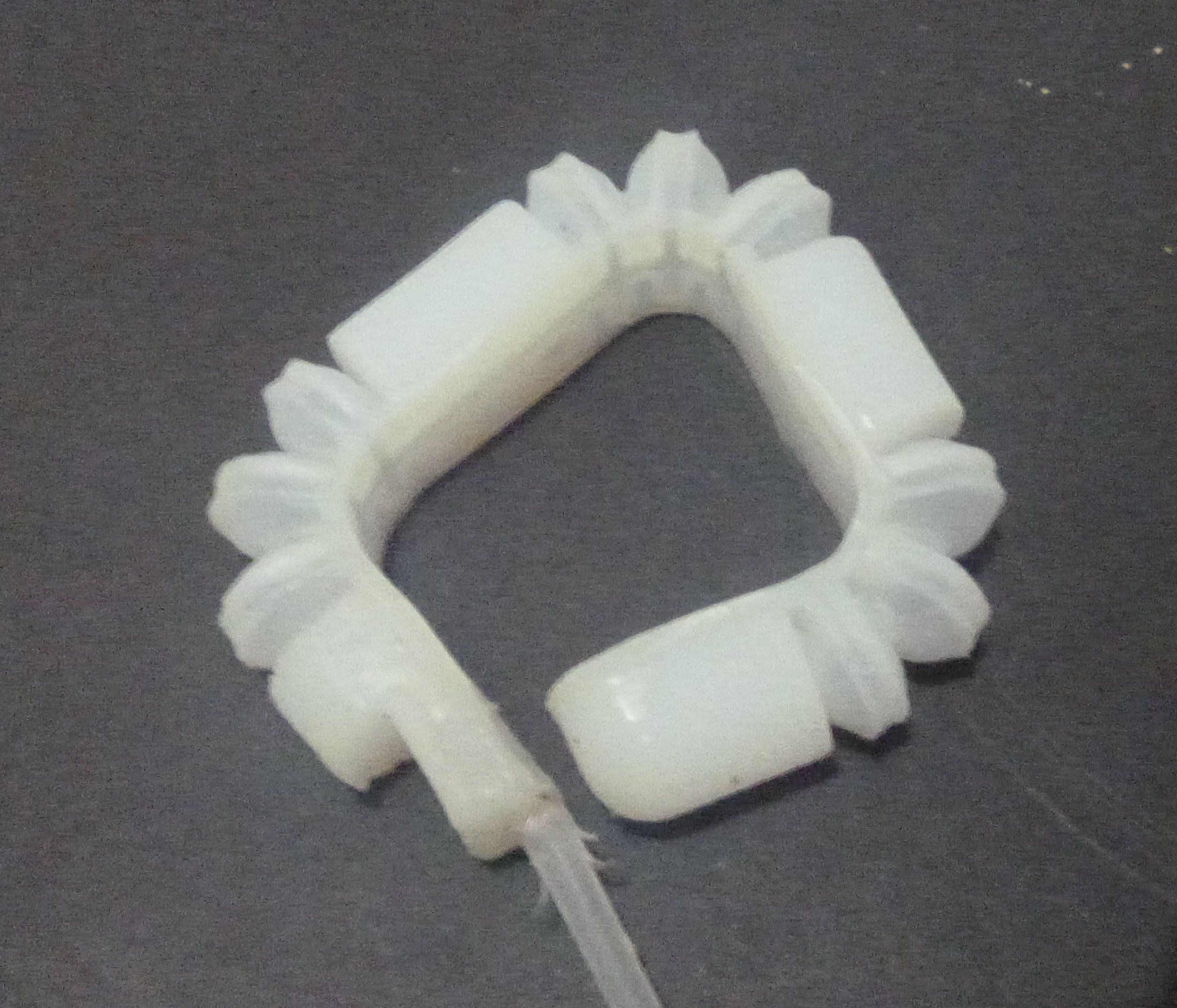
Softness is an important property of this hand, so soft robotics is clearly and inspiration with the mechanical functions being a direct response.
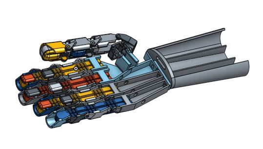
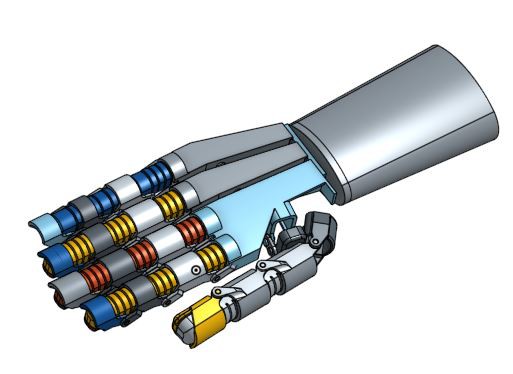
Link to the CAD models:
https://grabcad.com/library/soft-hand-1
Composition
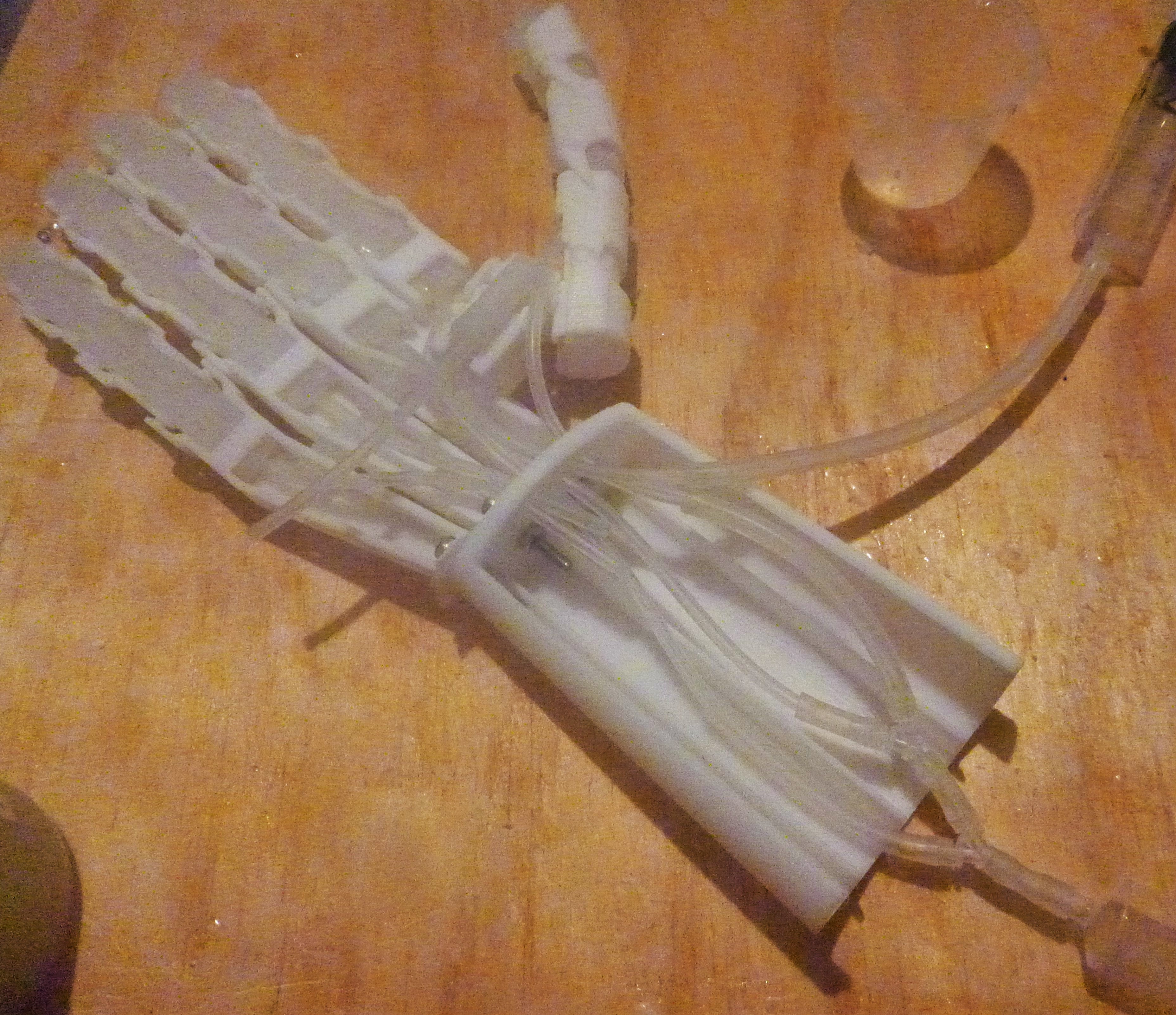
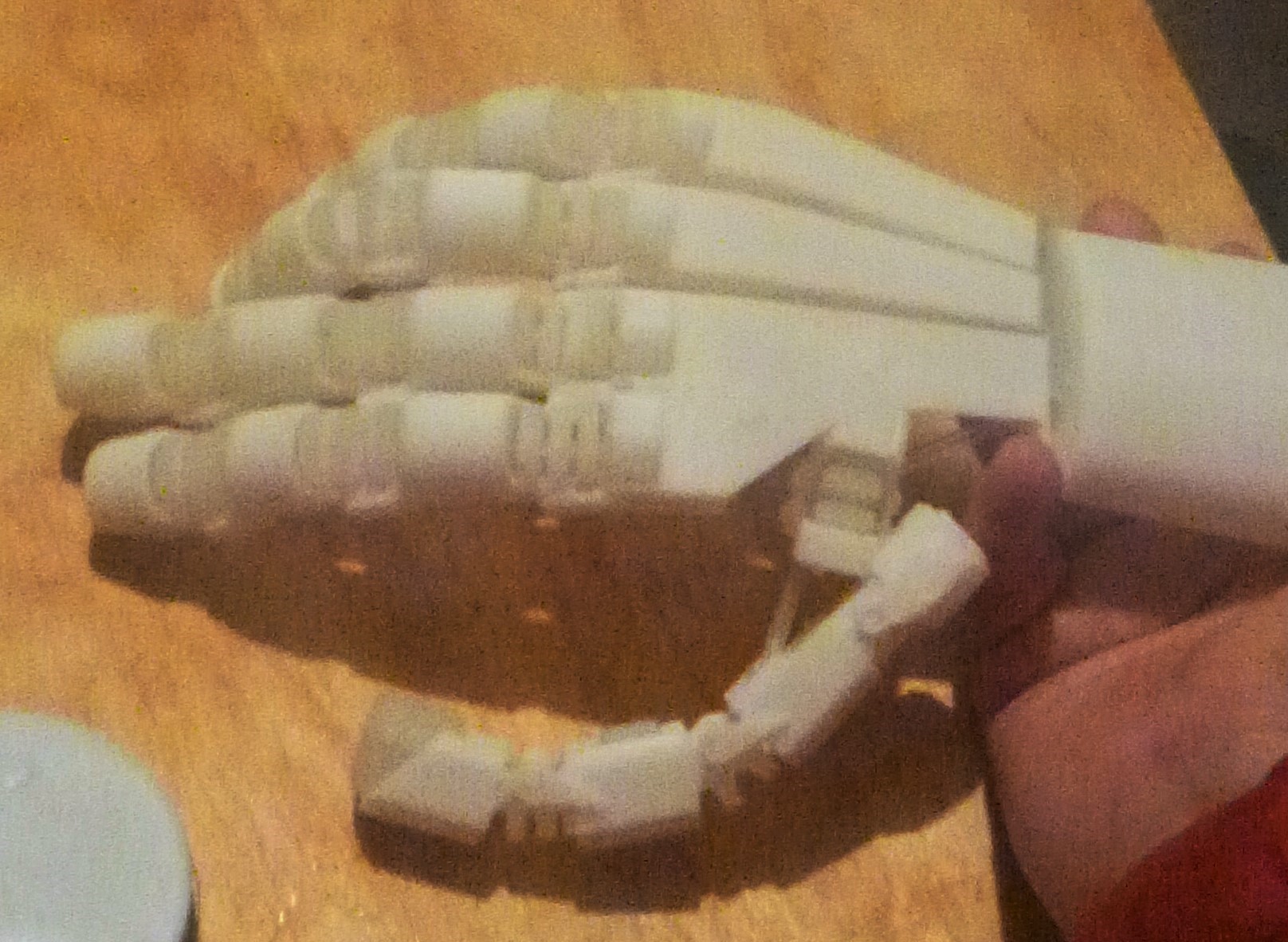
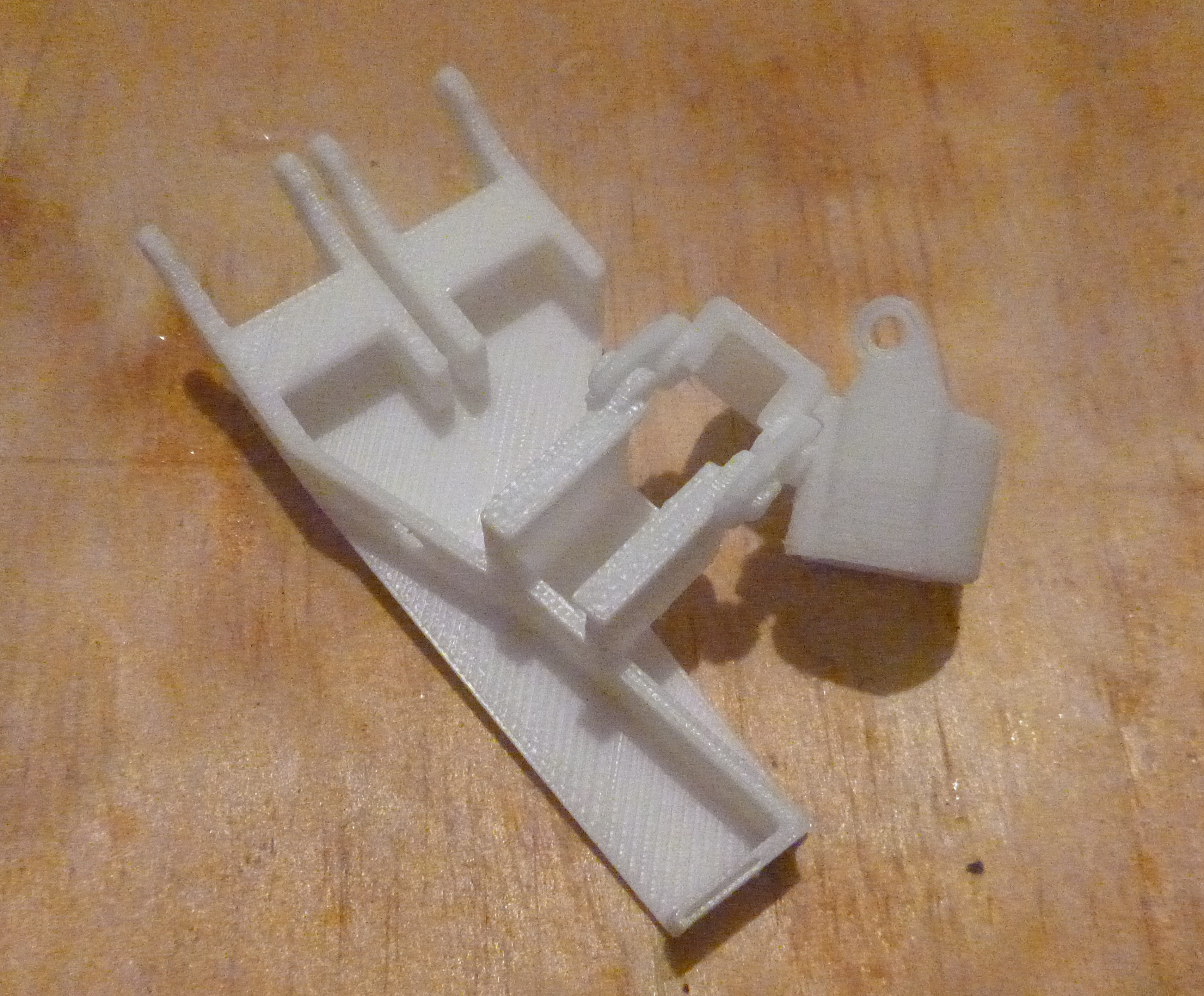
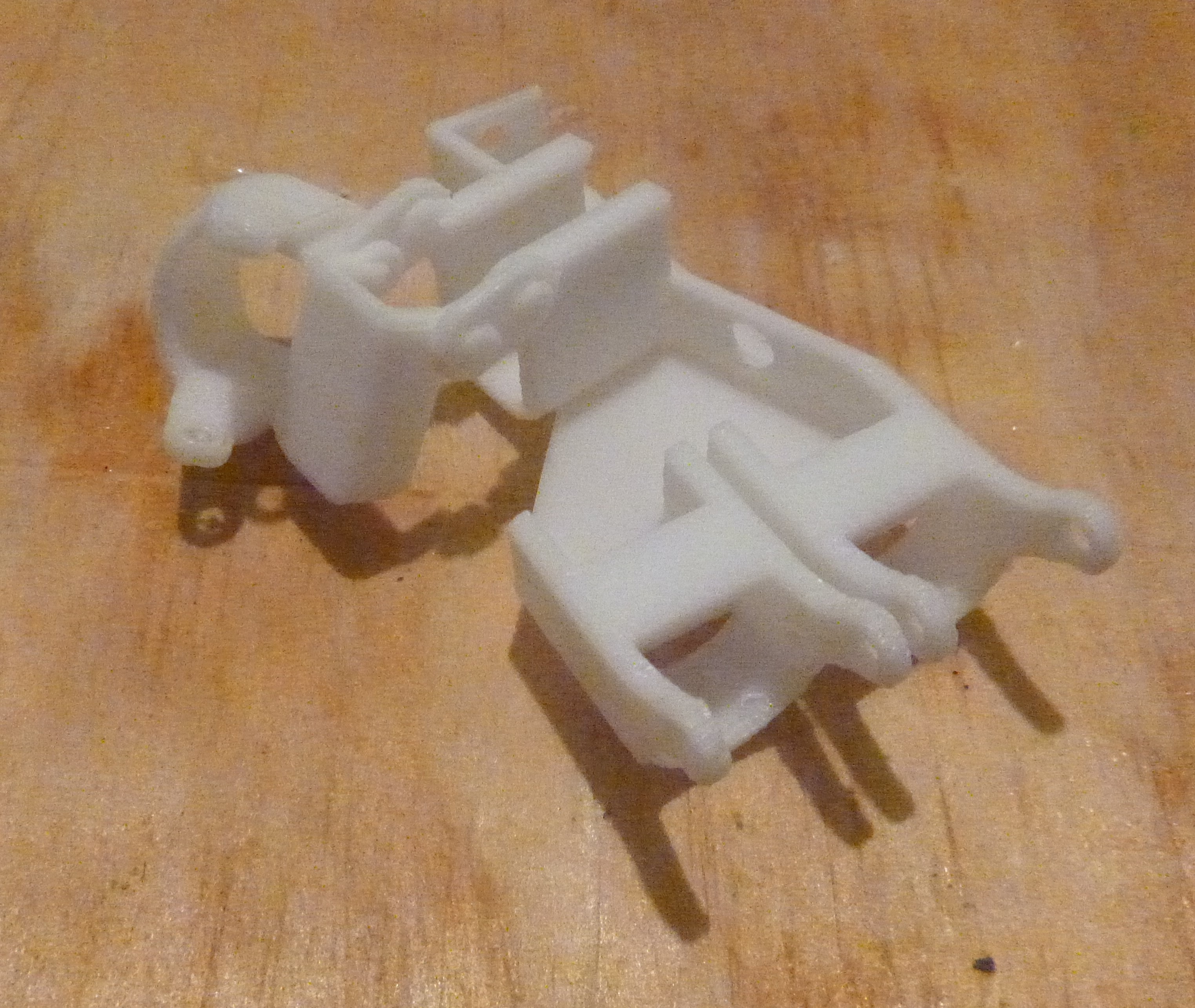
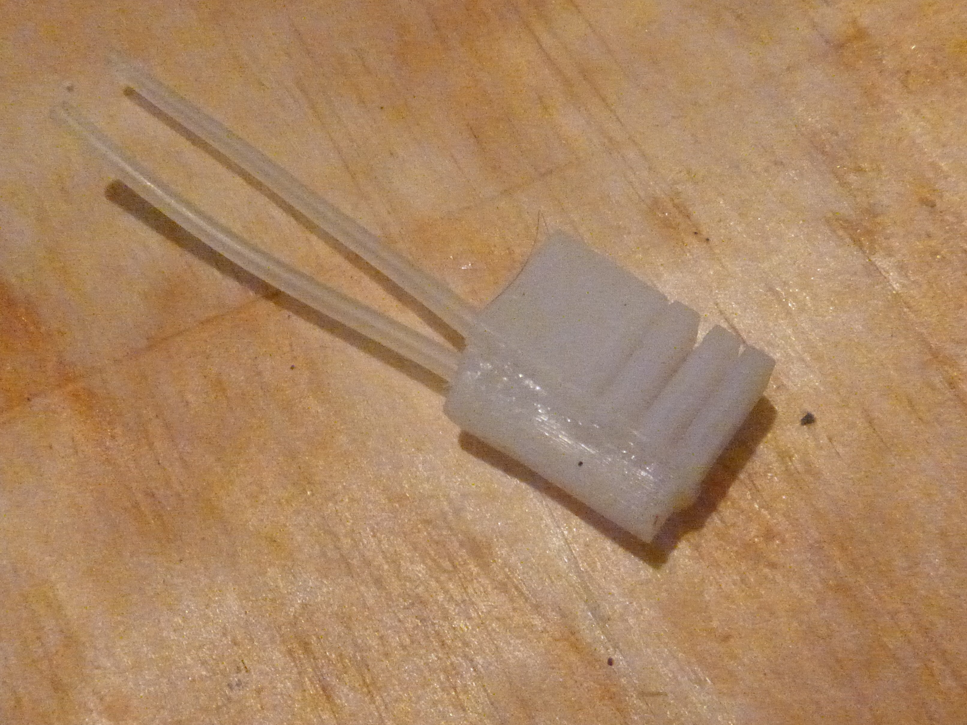
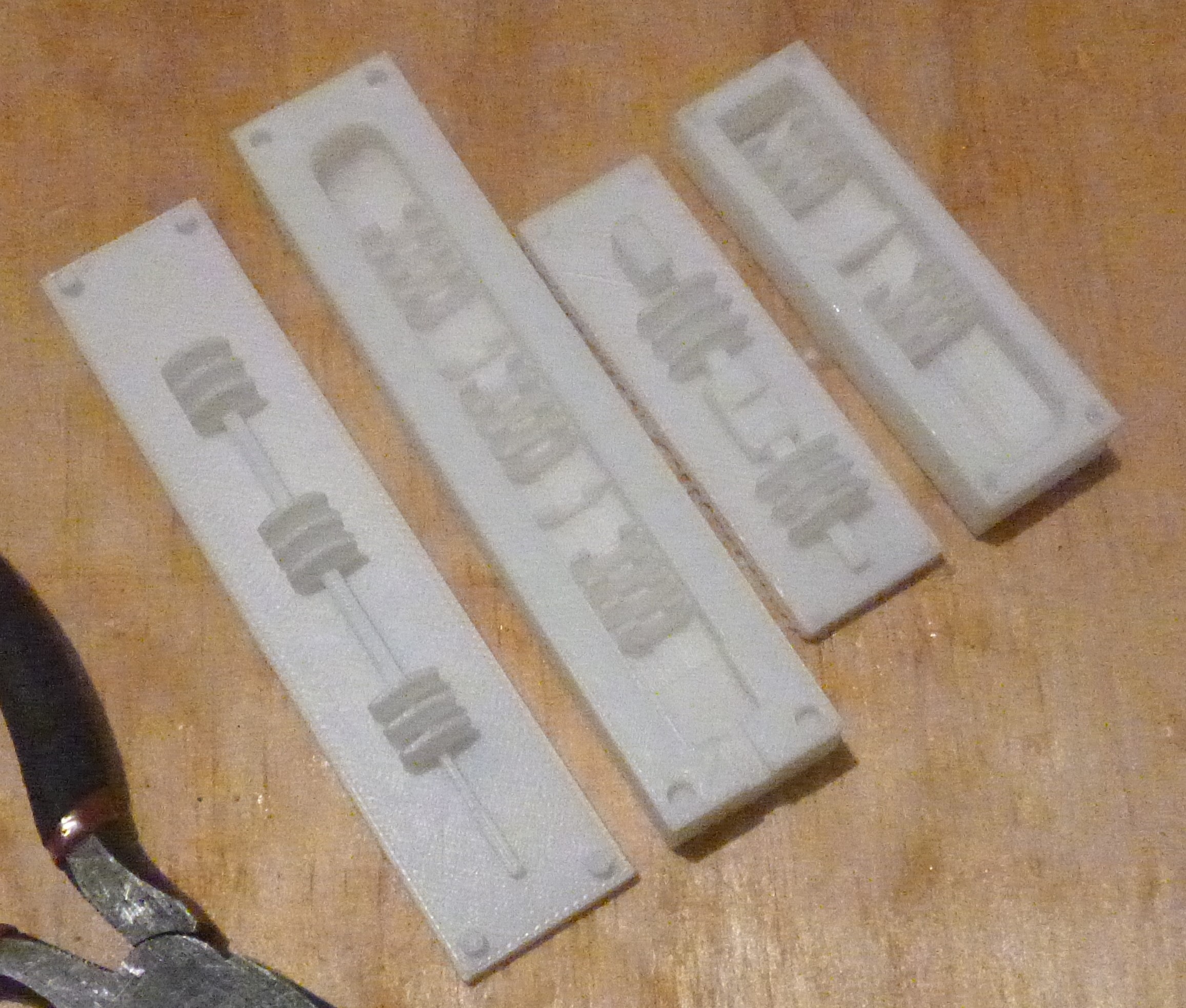
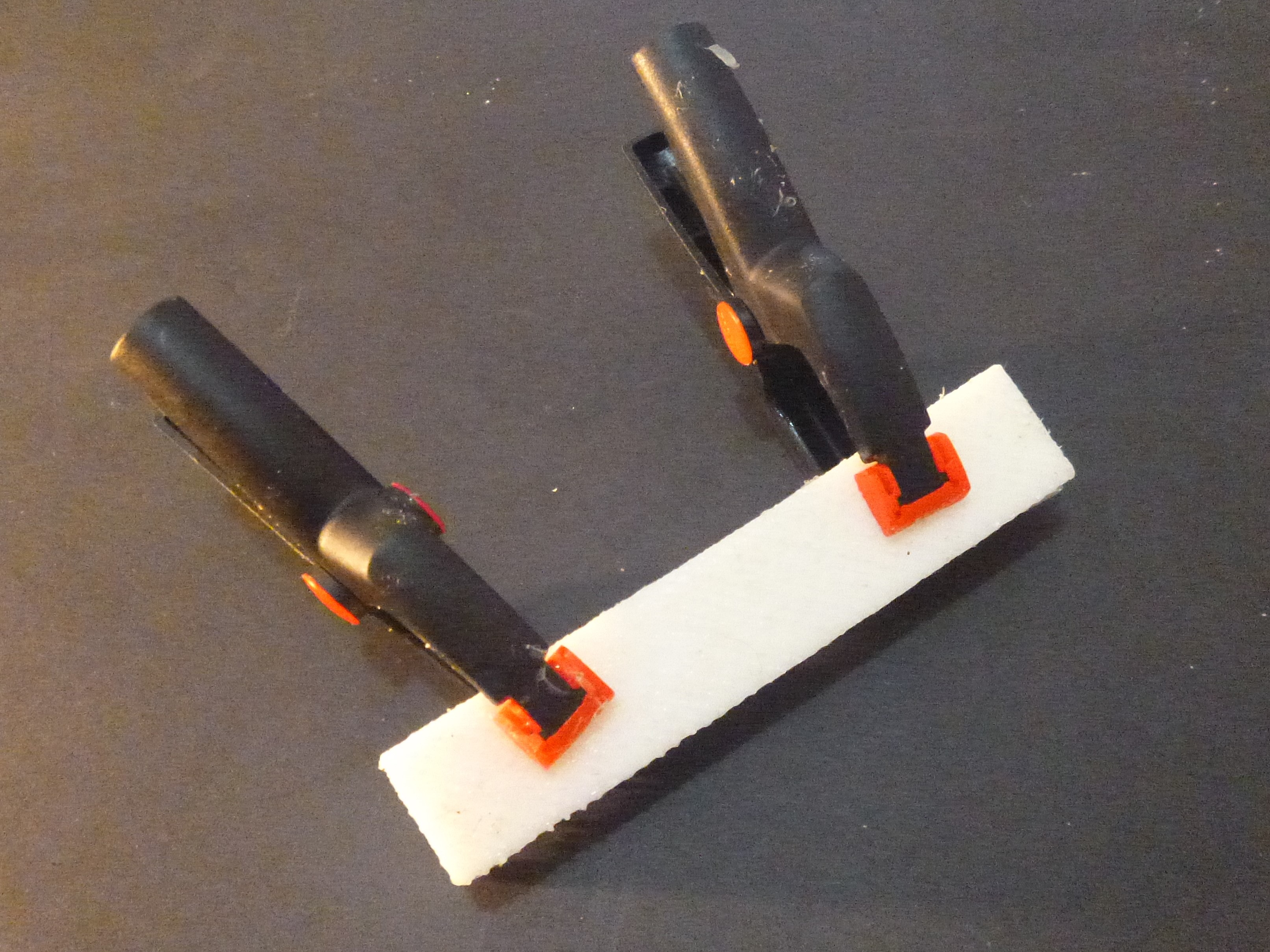
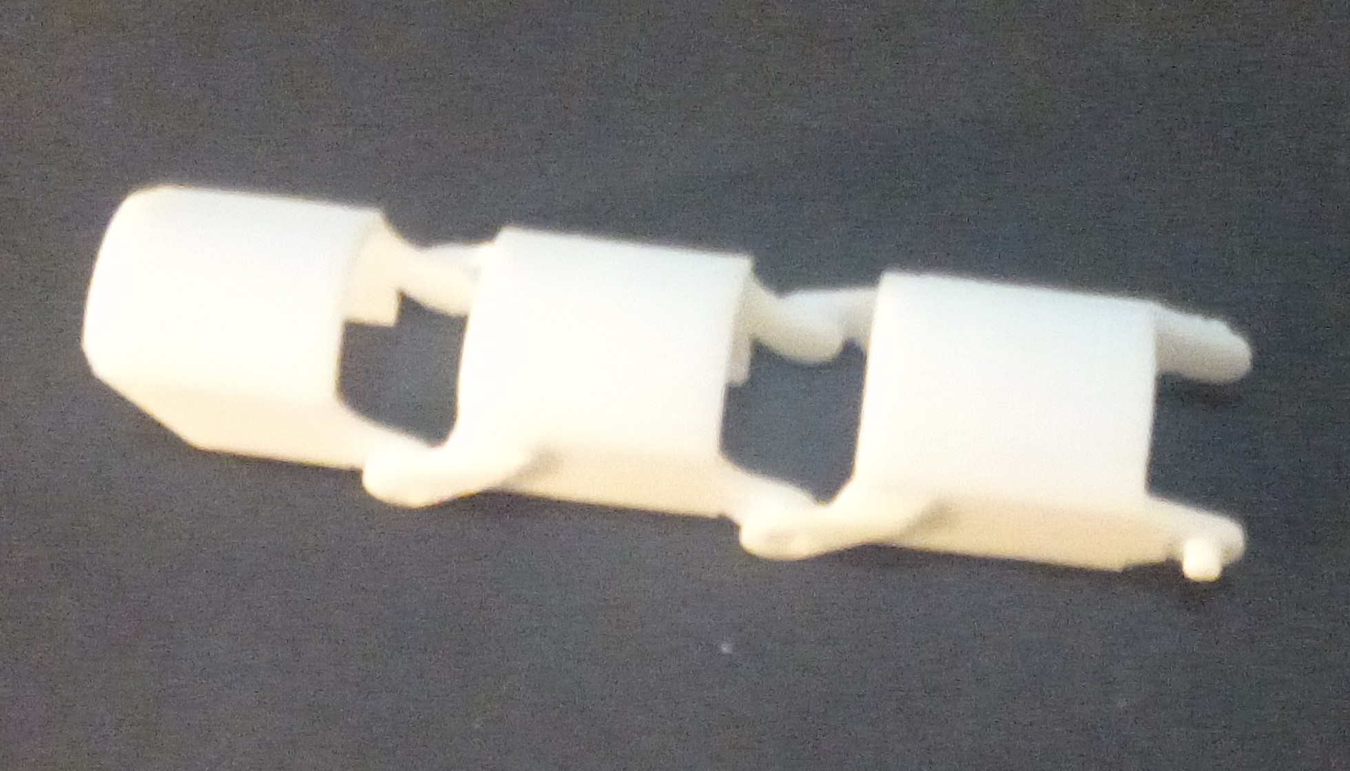
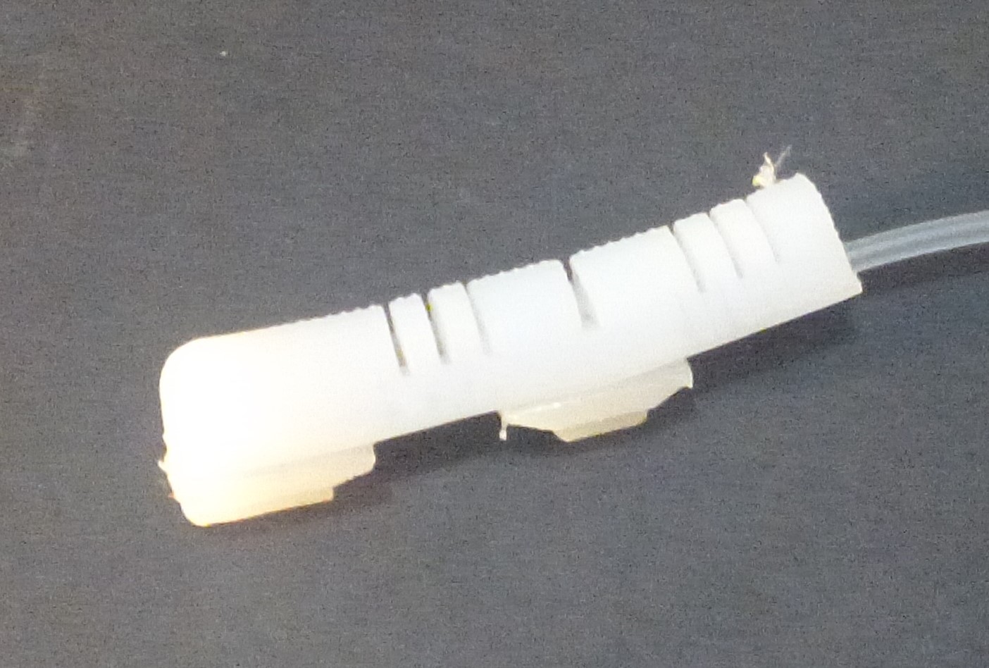
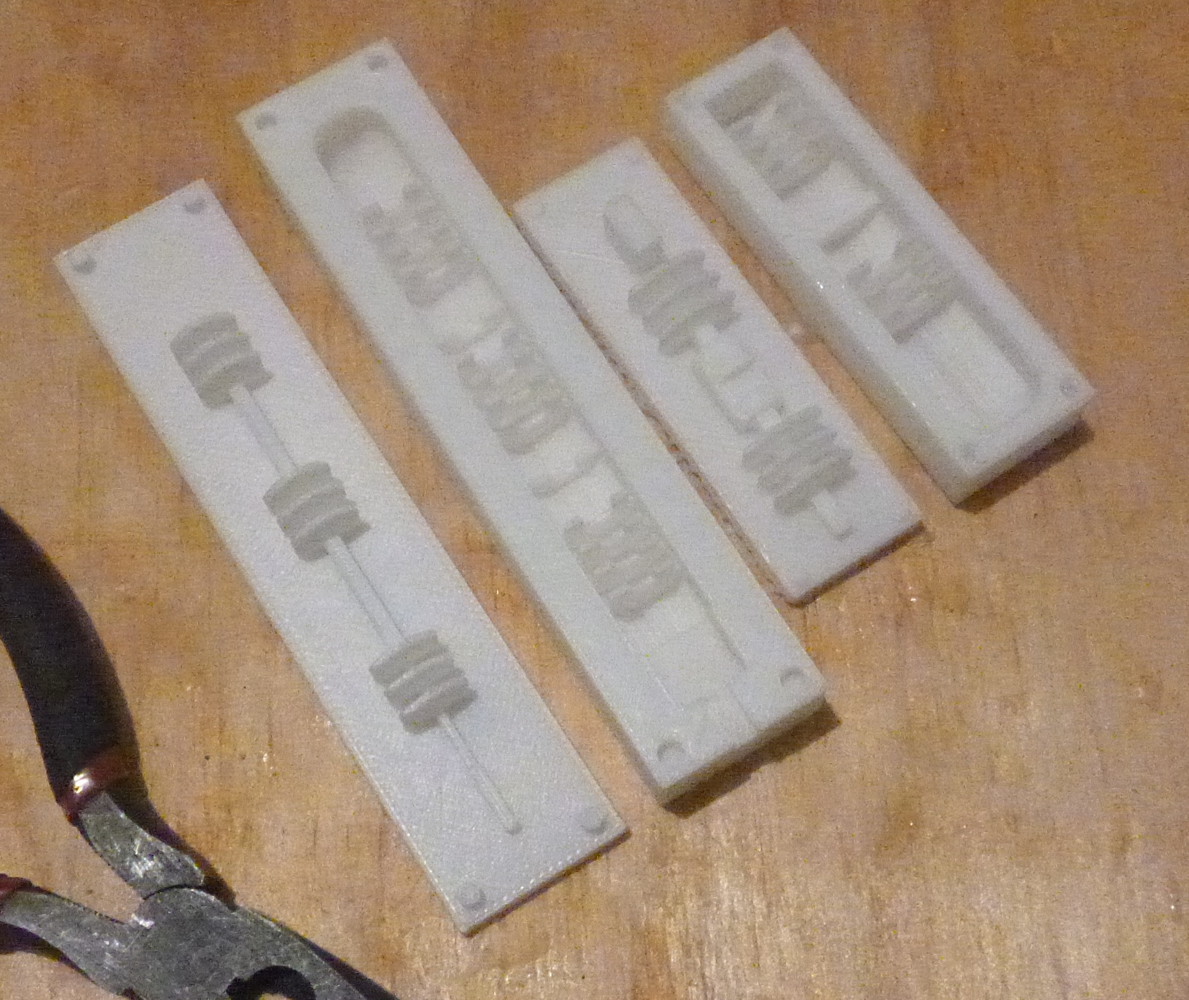
The hand comprises of a hard ABS 3D printed exoskeleton is a soft silicone core for control and actuation. Having a hard exoskeleton limits the degrees of freedom for the appendages much like an insect. Softness is essential if an object is to interact with a noisy environment with unpredictable angles and surfaces allowing compliance.
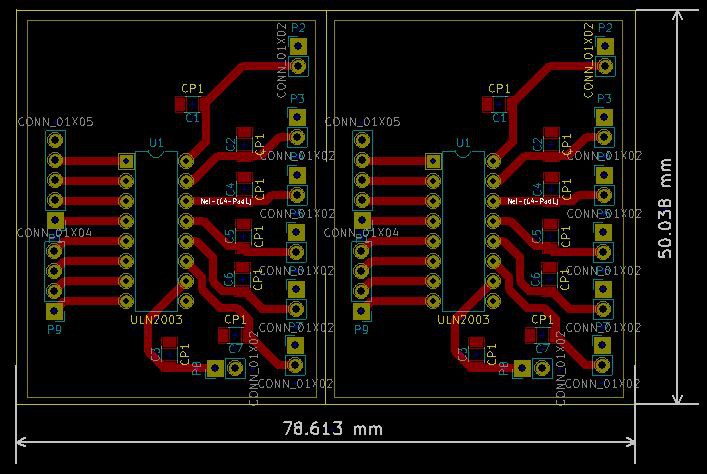
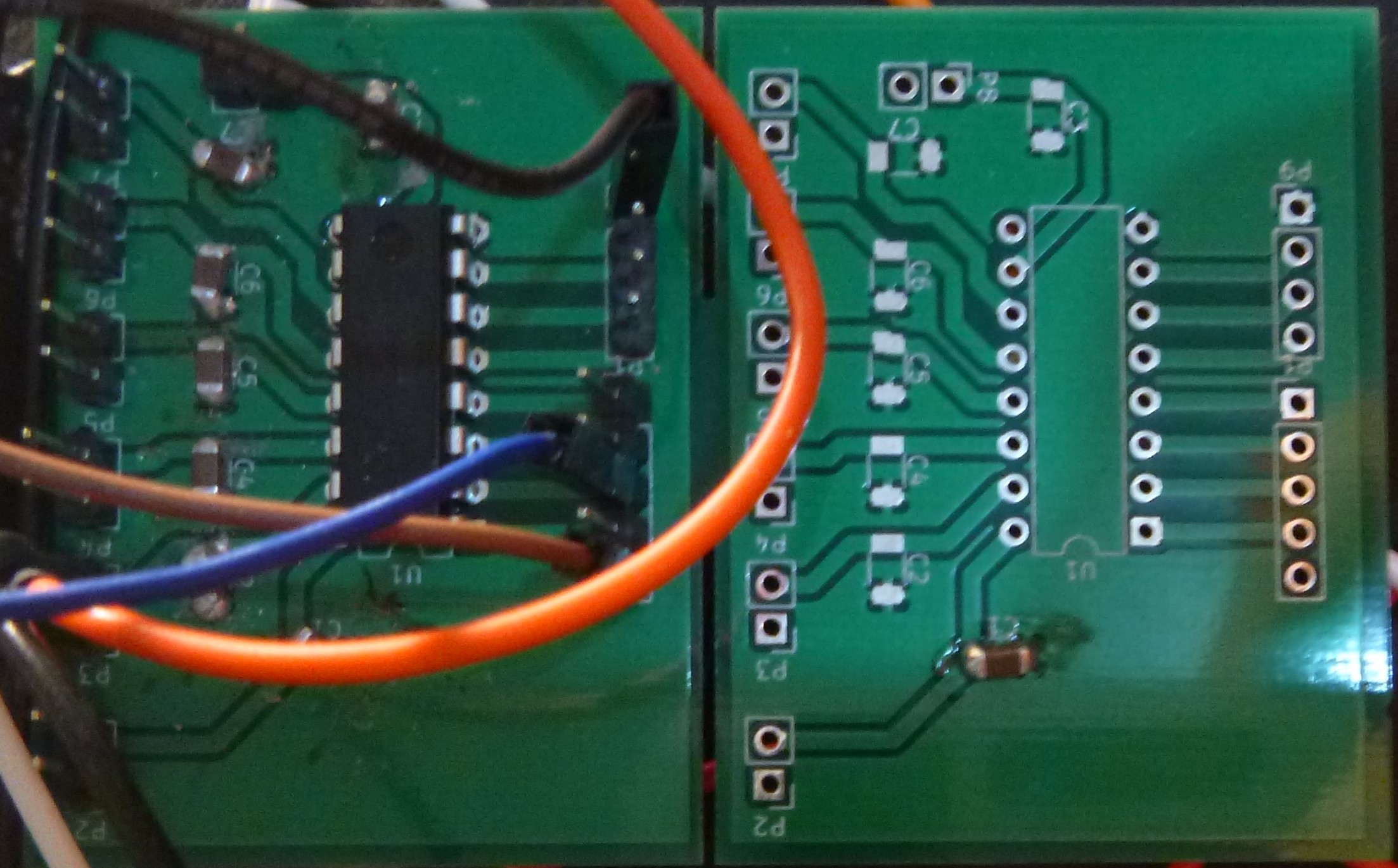
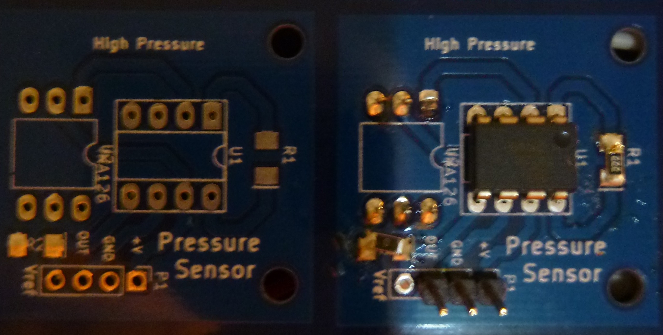
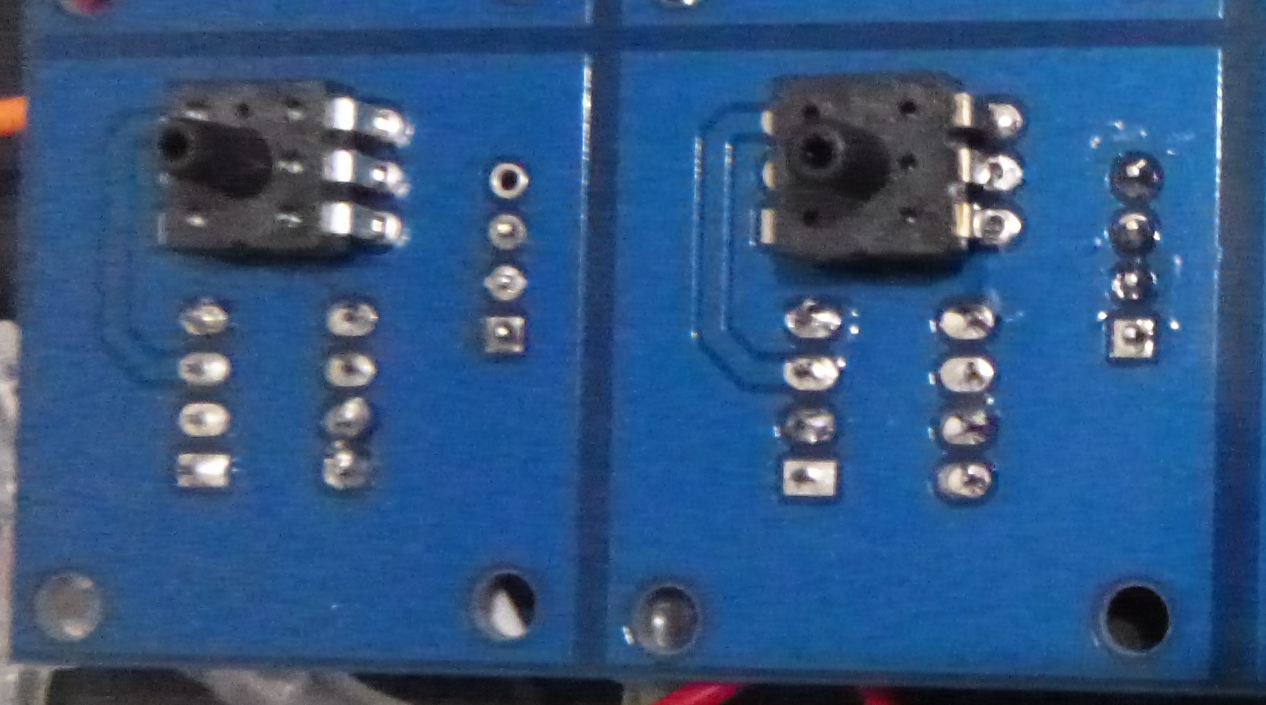
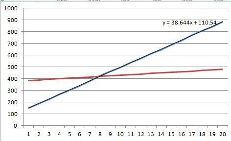
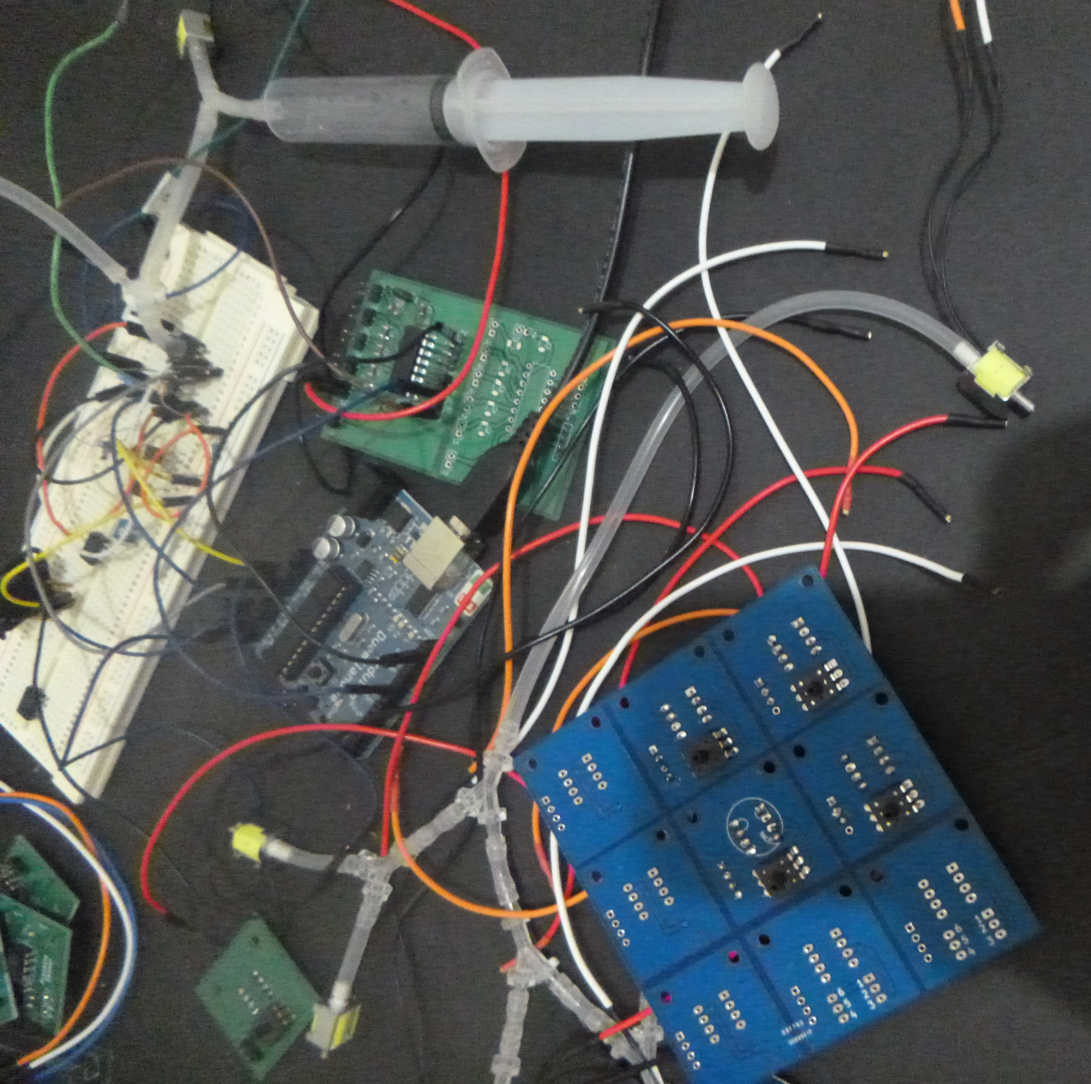
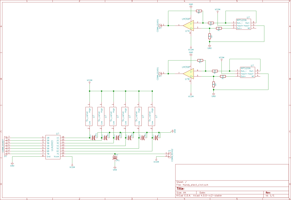
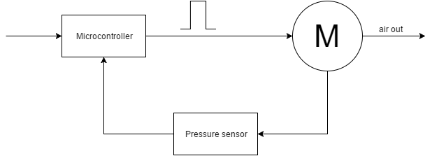
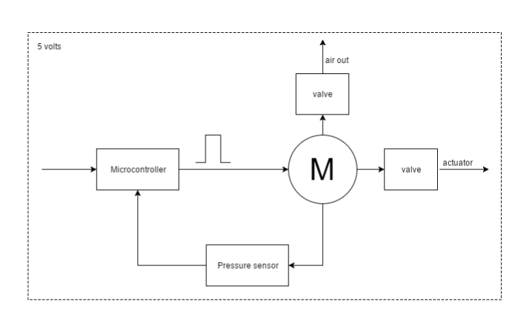
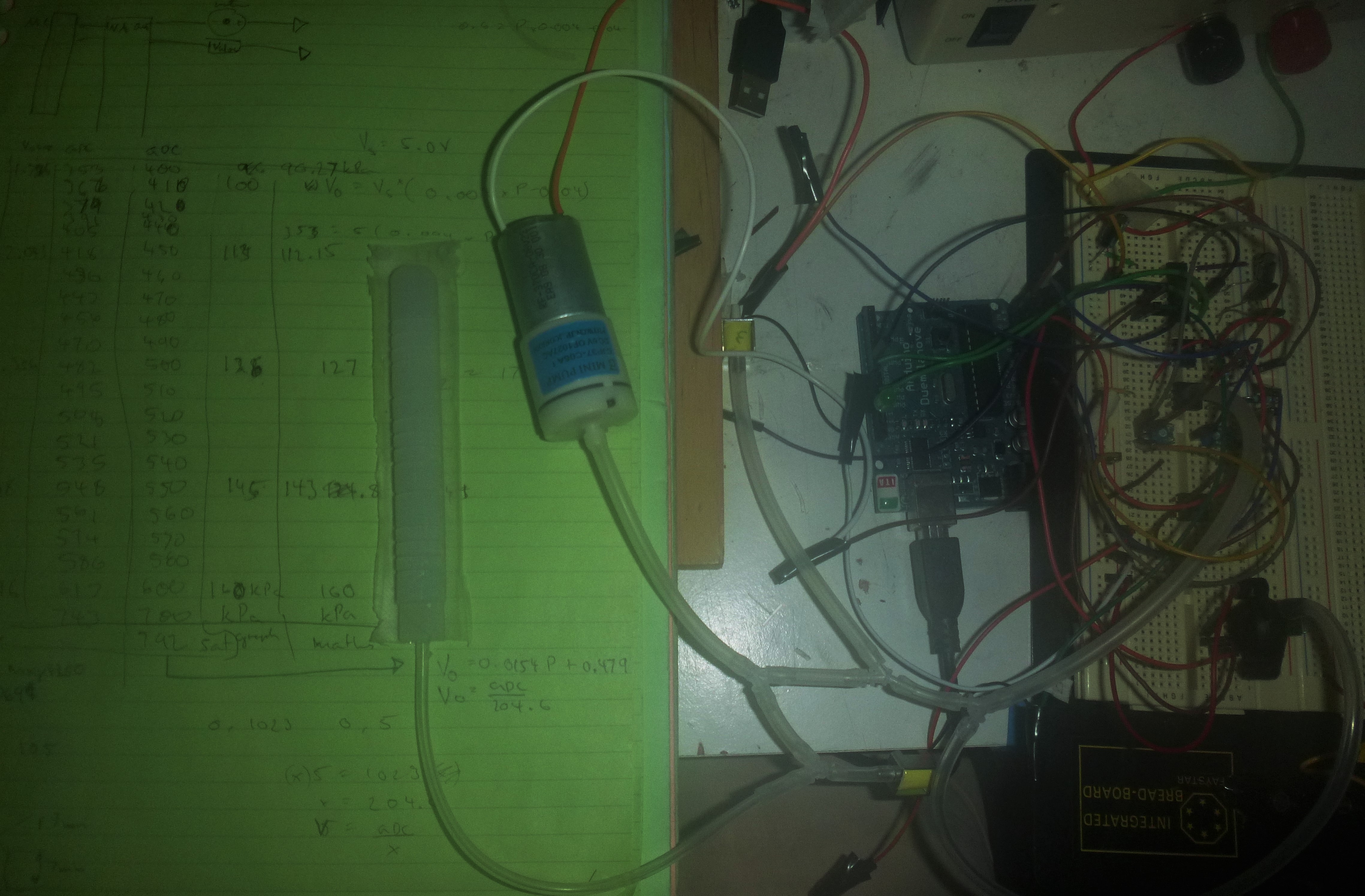
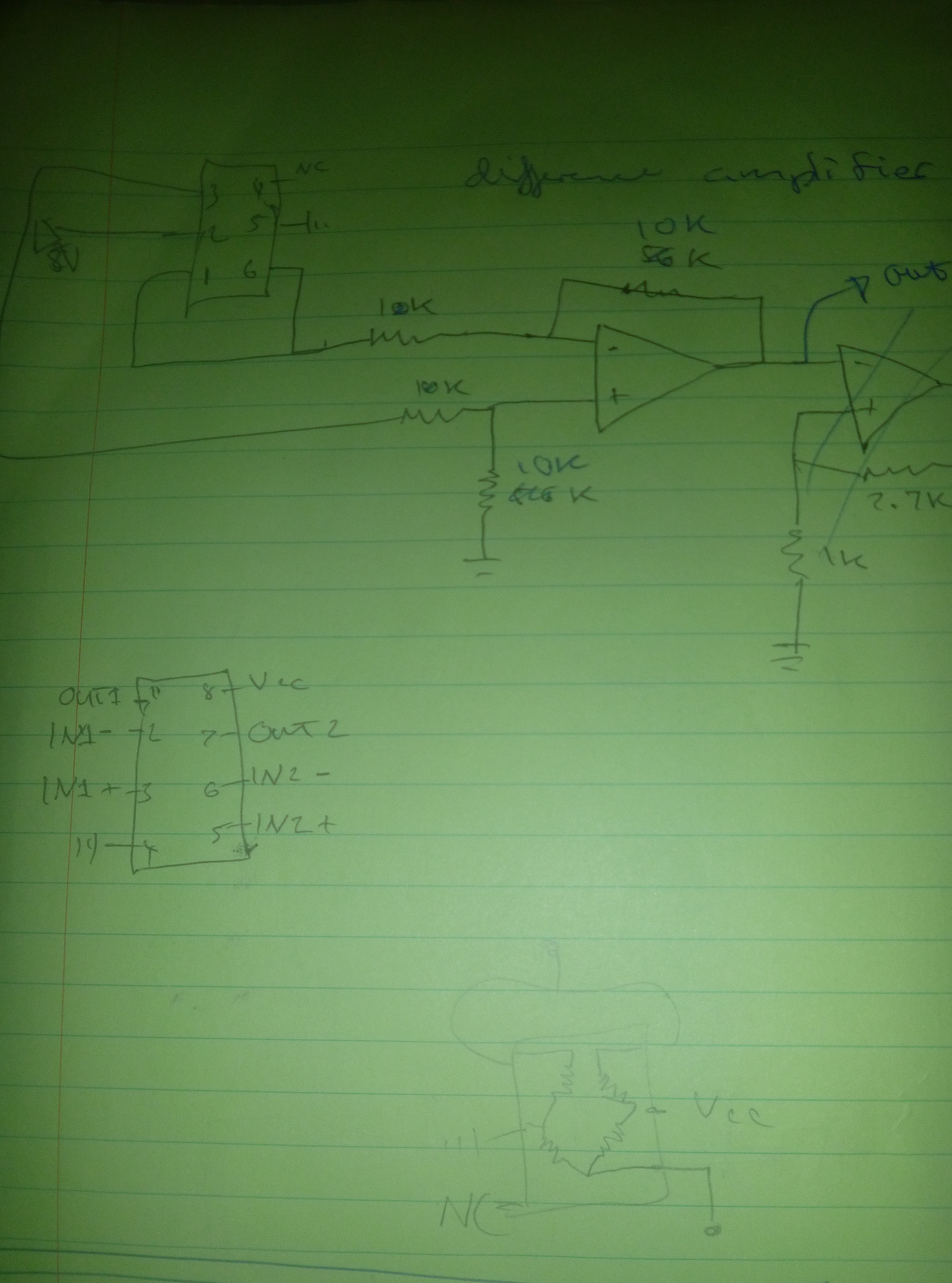
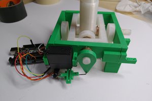
It will also have a control electronic with a pump, valves and sensors to give the hand a user friendliness. One each air line there will be a air pressure sensor and a solenoid inlet and outlet valve to regulate each fingers actuation and limit the amount of pressure.


 Matt Dombroski
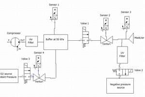
 Simon Harvey
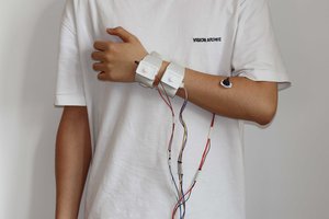
 HBChen-094
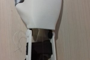
 Pauline Chevalin