Close
0%
0%

Analog TV Broadcast of the new Age

How to broadcast colored PAL television with a SDR transmitter.

Similar projects worth following
This projects describes my approach and success in transmitting an analog colored TV image via a rad1o (HackRF One).

In this post I explain the theory behind analog video transmission and how I implemented it using a relatively simple python script and GNU radio flow graph.

In order to understand what I do here, I recommend the SDR video series of Michael Ossmann and some videos of w2aew:

If there are any problems, errors or misunderstandings, please feel free to comment or DM.

pal.grc

This is the flow graph to transmit PAL video with a osmocom sink.

grc - 33.53 kB - 09/25/2016 at 18:12

Download

pal_generator_redo2.py

This file generates a y.out and a uv.out which are used in the GNU radio flow graph.

x-python - 5.53 kB - 09/25/2016 at 18:11

Download

  • 1 × rad1o, hackrf or similar SDR transceiver
  • 1 × general purpose sma antenna

  • GNU Radio FTW

    marble09/17/2018 at 14:11 2 comments

    Okay, I was wrong. It is entirely possible to implement PAL in GNU Radio and ffmpeg alone. The resulting GNU Radio flow graph looks something like this:

    In general: Top part handles the brightness (Y) and the bottom part handles the color (UV). The part to the right combines both again.

    The result looks something like this:

    Watch it on peertube.social

    Color is still to be fixed.

    The command line generating this:

    $ ffmpeg -i /home/marble/lib/Videos/bigbuckbunny.mp4 -codec:v rawvideo -vf 'scale=702:576:force_original_aspect_ratio=decrease,pad=702:576:(ow-iw)/2:(oh-ih)/2' -f rawvideo -pix_fmt yuv444p -r 50 - | ~/curr/Software\ Proejcts/video2pal/grc/pal_transmit.py 
    

  • Working on Video

    marble09/15/2018 at 23:22 0 comments

    Being able to transmit a still image is already quite fun, but of course I also want to be able to do moving picture.

    The algorithm that implements the generation of a still images was purely implemented in python. Although python is a nice langue, it's not very fast without any external help.

    I was thinking abut using numpy for matrix manipulation, but then I found out that ffmpeg can encode into raw YUV (aka Y Cb Cr) values.

    ffmpeg -i /home/marble/lib/Videos/bigbuckbunny.mp4 \
    -c:v rawvideo \
    -vf 'scale=702:576:force_original_aspect_ratio=decrease,pad=702:576:(ow-iw)/2:(oh-ih)/2' \
    -f rawvideo \
    -pix_fmt yuv444p \
    -r 50 \
    -

    This command not only transforms any video into a raw YUV stream and writes it to stdout, it also sets the frame rate to 50 fps, scales the video down to PAL resolution and applies letterboxing. For each video frame ffmpeg output a whole Y frame, then a U frame and then a V frame.

    I tried to the the rest purely in gnuradio-companion, but as it turnes out, this would be really hard and quite a mess. So I turned back to python for the adding of synchronization pulses etc.

    To use ffmpeg in python I use the subprocess module.

    #!/usr/bin/env python3
    import subprocess
    VISIB_LINES     = 576
    PIXEL_PER_LINE  = 702
    VIDEO_SCALE     = '{}:{}'.format(PIXEL_PER_LINE, VISIB_LINES)
    ffmpeg = subprocess.Popen(['/usr/bin/ffmpeg',
        '-i', '/home/marble/lib/Videos/bigbuckbunny.mp4',
        '-c:v', 'rawvideo',
        '-vf', 'scale=' + VIDEO_SCALE + ':force_original_aspect_ratio=decrease,pad=' + VIDEO_SCALE + ':(ow-iw)/2:(oh-ih)/2',
        '-c:v', 'rawvideo',
        '-f', 'rawvideo',
        '-pix_fmt', 'yuv444p',
        '-r', '50',
        '-loglevel', 'quiet',
        #    '-y',
        '-'],
        stdout = subprocess.PIPE) 

  • The Theory behind PAL (pt 2)

    marble09/25/2016 at 17:16 0 comments

    Encoding color

    YUV color space

    In opposite to the RGB color space that we as hackers are used to, the image in PAL is encoded in YUV color space. The Y componen (the luma) is described in part 1 of The theory behind PAL. The U and V component are just other names for the intensity of red and blue (also called chroma blue [Cr] and chroma red [Cb]). As a reference to linear algebra, this is merely a base change.

    [ Y ]   [ 0.299  0.587  0.114 ] [ R ] 
    [ U ] = [-0.147 -0.289  0.436 ]*[ G ] 
    [ V ]   [ 0.615 -0.515 -0.100 ] [ B ]
    The green information is not lost, but endcode in Y, U, and V all together.

    Simplified: Y = Cr+Cg+Cb <=> Cg = Y-Cr-Cb

    Modulation of U and V

    To modulate the chroma alongside the luma in the signal, a process called Quadrature Amplitude Modulation (QAM) is used. The Wikipedia has a really good explanation of the process. The modulated signal is then a subcarrier of the main video signal.

    Basically, what you can do, is have two scalar signals (our chroma values) and multiply each with two sinusoids having a 90° (π/2 [τ/4]) phase shift against each other. When you add these two resulting signal, you get a sinusoid which phase and amplitude depend on the value of the red and blue signal.

    To make this a little bit easier to grasp, I've put together a little something in GeoGebra. The black line is the reference sinusoid which the phase shift will be measured to. The red and blue dotted line are the two sinusoids which are the two signals will be multiplied to. The purple line is the sum of u*blue and v *red.


    As you can see, the change of the U and V signal result in a change of the the resulting signal towards the corresponding sinusoid. What we can do now of course is having a mixture of both.


    The math behind this is "simple" trigonometry. In the result the amplitude of the chroma signal is

    And the phase is

    Resulting in

    The formulas are especially interesting for demodulation, because now you derive the ration between red and blue from the phase angle

    and the the brightness of both of these from the amplitude of the signal.

  • The Theory behind PAL (pt 1)

    marble09/19/2016 at 08:11 0 comments

    In order to understand the structure of a PAL/NTSC signal, it's a good idea to understand the structure of a grayscale image signal first. The reason is that PAL and NTSC needed to be downward compatible and therefore interpretable by older b/w TV sets.

    To keep writing simpler I will continue to only use "PAL" instead of "PAL/NTSC" and will add the distinction when needed.

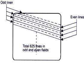
    Visible Scan Lines in a monochrome signalGrayscale TV signals only transmit the brightness - the luma - of the image. This is simply encoded in the strengt of the signal. The higher the voltage, the brighter the point in the image. The way the image is build up is by multiple scan lines. You draw many lines one after the other and you get an image.


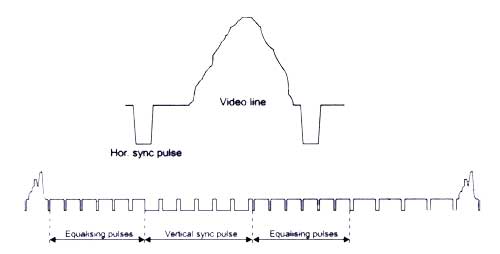
    Voltage over Time of the SignalEach line is a waveform which represent the luma along the line. To keep the image aligned with the screen, h-sync ans v-sync pulses are used.


    Interlacing

    To maintain a high resolution and a high frame rate of 50 fps, the simple trick of interlacing lines is use. This means, that in the first 20ms only the odd lines are drawn and in the next 20ms the even ones. The only drawback of this is that motion blurr is now more visible and a scene change not as smooth.


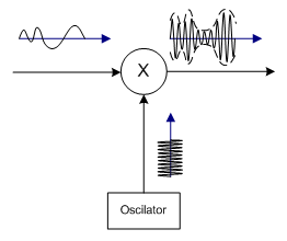
    Transmission of the signal is done by amplitude modulating it onto a carrier wave.

    "In amplitude modulation, the amplitude (signal strength) of the carrier wave is varied in proportion to the waveform being transmitted." - Wikipedia

    In digital signal processing this can be done by multiplying both signal.

View all 4 project logs

Enjoy this project?

Share

Discussions

jvincenzo wrote 07/28/2021 at 12:04 point

This is looking very impressive idea I am also working on a similar type of idea and looking to share it with you guys click on getflink.

  Are you sure? yes | no

wadwin wrote 06/18/2020 at 20:57 point

Hi dude Great Job :D

I fail using pal_generator_redo2.py can you help me to create y.out and uv.out ?

You are talking about pal_transmit.py where can we find the file ?

Thx

  Are you sure? yes | no

surpscare wrote 04/04/2020 at 17:05 point

Hi! Can I ask you about what specs do your PC have?
I tried to reproduce tediously the given flow graph (holy cows it's large) and instantly got a bunch of errors, which is all about buffer allocation failure, and one more which says:
Error 1455: The paging file is too small for this operation to complete.
So I wonder what should be minimum RAM/CPU/swapfile ammount to handle such big memory allocations.


  Are you sure? yes | no

KD9KCK wrote 10/02/2018 at 21:45 point

Do you think this could work with NTSC with a bit of editing?

  Are you sure? yes | no

marble wrote 10/03/2018 at 11:44 point

I guess. The modulation is kinda the same. one would have to edit some parameters like the line count and pixels per line i would think and also remove the phase alternation.

  Are you sure? yes | no

veso266 wrote 04/07/2017 at 19:38 point

Hi do you think you could provide me with your y.out and uv.out files because I think my are broken as I only get 4 black bars on my tv

Thanks for helping and Best Regards

  Are you sure? yes | no

Thomas wrote 10/06/2016 at 05:32 point

Couple of weeks ago this idea popped up and I wondered if someone else already do it, found nothing until today ! You have my interest ! I got a SDR kit based on LMS6002 and Cyclone V, what's the burst reference frequency ?

  Are you sure? yes | no

marble wrote 09/18/2018 at 09:17 point

For PAL this frequency is 4,43361875 MHz

  Are you sure? yes | no

Does this project spark your interest?

Become a member to follow this project and never miss any updates