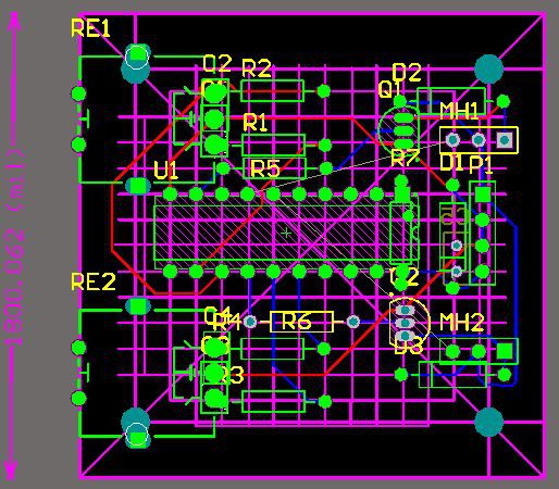
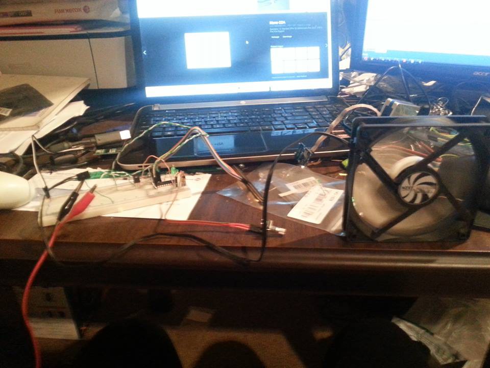
Close
0%
0%

Cheap PC PWM Fan Controller

A two channel fan controller utilising an Atmel AVR ATtiny2313 and Rotary Encoders.

foxFox
Similar projects worth following
Wanting to have a home project to keep myself occupied, a friend mentioned he wanted a controller for his front 3 Pin PC case fans. I took the opportunity with both hands as it also gave me a chance to learn about rotary encoders and start building up my own AVR libraries for external peripherals.

This fan controller uses both the 12V and 5V rails on the PSU. By doing this, the component count could be reduced (i.e not having to add a linear regulator and capacitors). One thing that I should add is that I happened to have a prototyping board and berg connector lying around so that would have reduced the cost also.
Breadboards and jumpers also make the programming part easier.
The idea behind using rotary encoders was they take a lot more punishment than pots. Also noting that there is not an ADC on the 2313 chip so a pot would not have worked anyway.

  • 1 × Berg Connector molex to berg connector adaptor to power the board.
  • 2 × Molex 3 Pin Headers For the fans to plug onto.
  • 1 × 4x2 Row Header Pins For the Berg Connector to clip onto
  • 2 × NPN Transistors (I used PN2222ATA) Used to switch the 12V supply to the fans. Alternatively I'm certain two FETs could be used instead.
  • 5 × 100nF Ceramic Capacitors (aka 0.1uF) For filtering the encoder bounces and decoupling the avr power supply.

View all 13 components

  • 1
    Step 1

    Assuming you now have all of the parts available at your disposal (plus a few spare just in case - you know how sods law is). Start with looking at how you are going to lay out the parts and wire/solder them up. 

    I probably went overboard by using a circuit board editor and actually creating the layout for my prototype board. At least by doing this I could see how large the components would be and how they would sit. 
    Comparing with the actual parts also helped in laying it out cleanly.
    All else fails, scratch it up on a piece of paper. In the above pic, blue runs were mainly component wired. Red runs were with CAT5 copper wire.

  • 2
    Step 2

    Now you know how this is going to look and is a layout you are happy with. The next step is to wire up the AVR micro into a breadboard and use jumpers from the correct ISP pins to connect to the programmer. Consult the datasheets for the correct pinout (I might expand on this later). 
    NOTE: When programming, ensure you untick the CLKDIV8 fuse otherwise it will only be at 1MHz - and be too slow for a decent PWM to the fans.
    I took things a step further and wired up an encoder and a LED off of the corresponding PWM Channel, just so I could see the dimming/brightening of the LED.

  • 3
    Step 3

    Now that you've used the attached code (I'm going to assume you have anyway...) have a play if you like to ensure all is going smoothly. 

    This is everything hooked up on a breadboard.

    Otherwise, it's time to assemble the finished product!

View all 9 instructions

Enjoy this project?

Share

Discussions

Fox wrote 01/15/2016 at 22:53 point

My apologies, these are in fact quadrature encoders. What I was trying to point out was the basic fundamentals are the same. You are still detecting a change/pulse and working from there. Although the angles between are different. I won't remove the grey code tag because it still provides a basis for how an encoder works.

  Are you sure? yes | no

James Newton wrote 01/15/2016 at 18:03 point

I'm looking for more on Gray Code encoders... you mention them here but I don't see where you used them. Have you heard of single track gray codes?

http://techref.massmind.org/techref/io/sensor/pos/enc/greycodes.htm

  Are you sure? yes | no

[deleted]

[this comment has been deleted]

James Newton wrote 01/15/2016 at 22:34 point

The link was to my page on single track gray codes. I'm very expanded on those, thanks anyway. FWIW: The bourns encoders are quadrature, not gray. Best wishes.

  Are you sure? yes | no

Similar Projects

Does this project spark your interest?

Become a member to follow this project and never miss any updates