 Vinch
VinchSensing Method
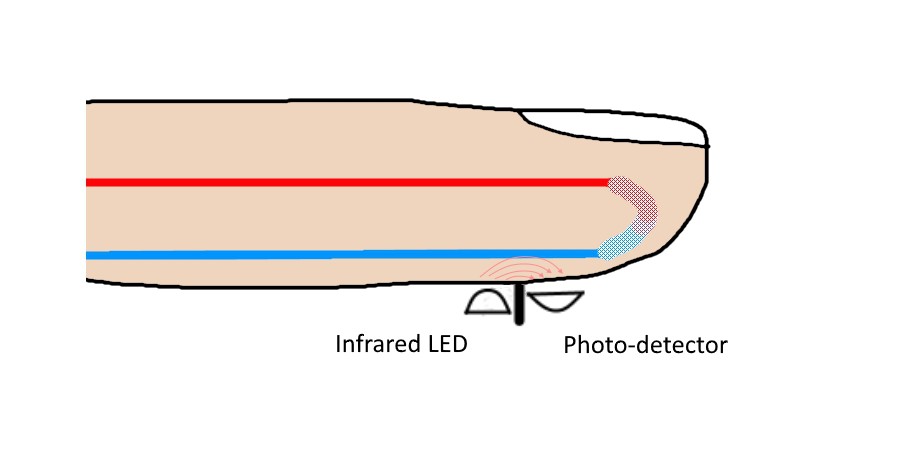
The sensor will be based on the classical infrared reflection method (photoplethysmography or PPG).
Initially I planned to use a piezo sensor for its low cost and low power consumption (passive sensor). The method is described in this interesting post and the same sensor is employed in the THS project. However, my own experimentations showed that it works fine, sticking the sensor on the finger, as long as you remain still. But once you move quickly the finger or try to hop, the measurement is so disturbed by the vibrations that it becomes impossible to recover the heart rate, even with a good filtering and signal processing. As the goal of this project is also to use the sensor for sport training, I turned to PPG method.
Hardware Platform
In addition to an IR emitting LED and a phototransistor for the PPG, we mainly need a micro-controller with a good ADC and a Bluetooth LE connection. Hopefully, I have another on-going project, Triggy, whose prototype board can perfectly address these needs - by the way, I can only advise you to have a glance and follow or like this project ;). It embeds the Nordic nRF52832 which is an ARM Cortex-M4 + BLE connectivity. Another benefit over other development boards is the size of the Triggy module, which is not far from what could be the final heart-rate monitor optimized form factor.
The sensing part is composed of the TCRT1000 reflective optical sensor, a bipolar transistor to drive the LED and some resistors. The TCRT1000 has the advantage of embedding the IR LED and the phototransistor on the same chip, with a physical isolation between them. This sensing part is connected to the Triggy board through its expansion connector. Four wires are needed: Vcc, ground, command and sensing. The schematic is shown below.
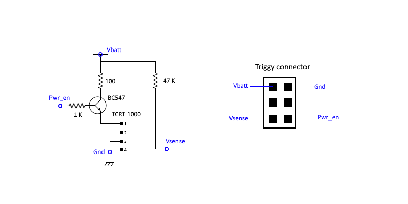
I decided not to add filtering or amplification on this sensing board, but instead to do everything inside the micro-controller. This strategy gives more flexibility on the filtering parameters and lightens the hardware.
First experiments
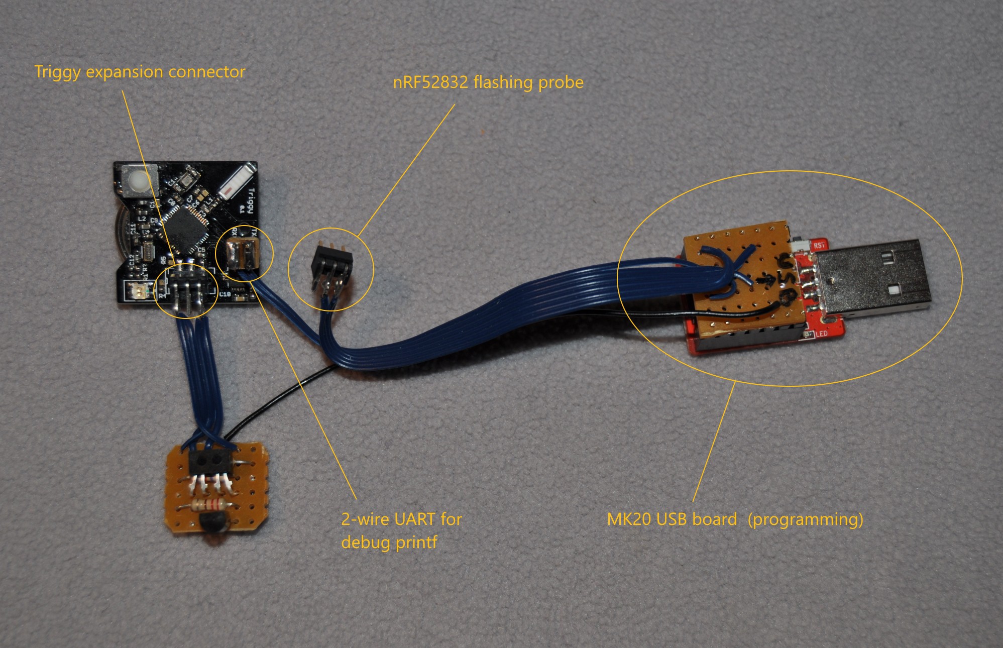
The picture below shows the whole hardware configuration allowing to measure and display the samples on a computer and in real-time . The red board is the MK20 USB board from RedBearLab which is utilized both to flash the nRF52832 firmware and to do the UART to USB bridge. Once plugged to a computer USB port (and driver installation), a serial terminal can be used to interact with the board.
I put the Triggy board and the sensing board on my finger and attached them with a velcro strip, in order to be close to real conditions. Note that heart rate signal is worse when the sensor is put at the base of the finger instead of at its tip.
For the first tests, the firmware embedded on the nRF52832 will basically perform ADC measurements at 64 Hz frequency and send the value over UART. About 120 us (empirical value) before the measurement the IR led command signal is raised, allowing the BC547 transistor to deliver current to the LED. The pulse is stopped right after ADC measurement is over. 120 us is the best pulse duration compromise between signal strength and mean power consumption.
In order to see the ADC measurements directly on a graph, I used the serial monitor provided by the Arduino IDE. From there, I could visualize in real-time my heart rate. However the signal obtained is noisy and contains a high DC component as no filtering is implemented in hardware. In the next section I give details on the signal processing used.
Heart rate extraction
The heart rate (beats per minute) is simply obtained by measuring the time between two consecutive peaks. Unfortunately the raw signal does not allow to do this operation with a simple algorithm. That's why a low-pass filtering and high-pass filtering should be applied to it, removing respectively the high frequency signals and noise (higher than ~4Hz) and the DC component.
I have implemented and tuned these filters in Matlab language and applied them to a signal recording. See extract_bpm.m...
Read more »
 Ever
Ever
 Johannes
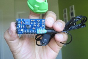
 Rajendra Bhatt
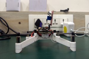
 Tanmay Karpe
Hi, congrats on this interesting project! Could you please explain how to program the microcontroller and the BLE module for newbies?
Thanks a lot!