 Alex
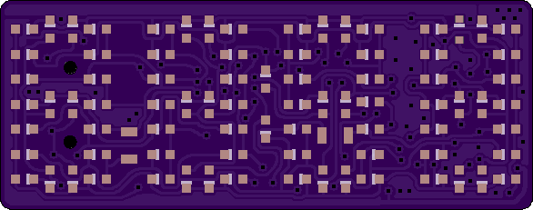
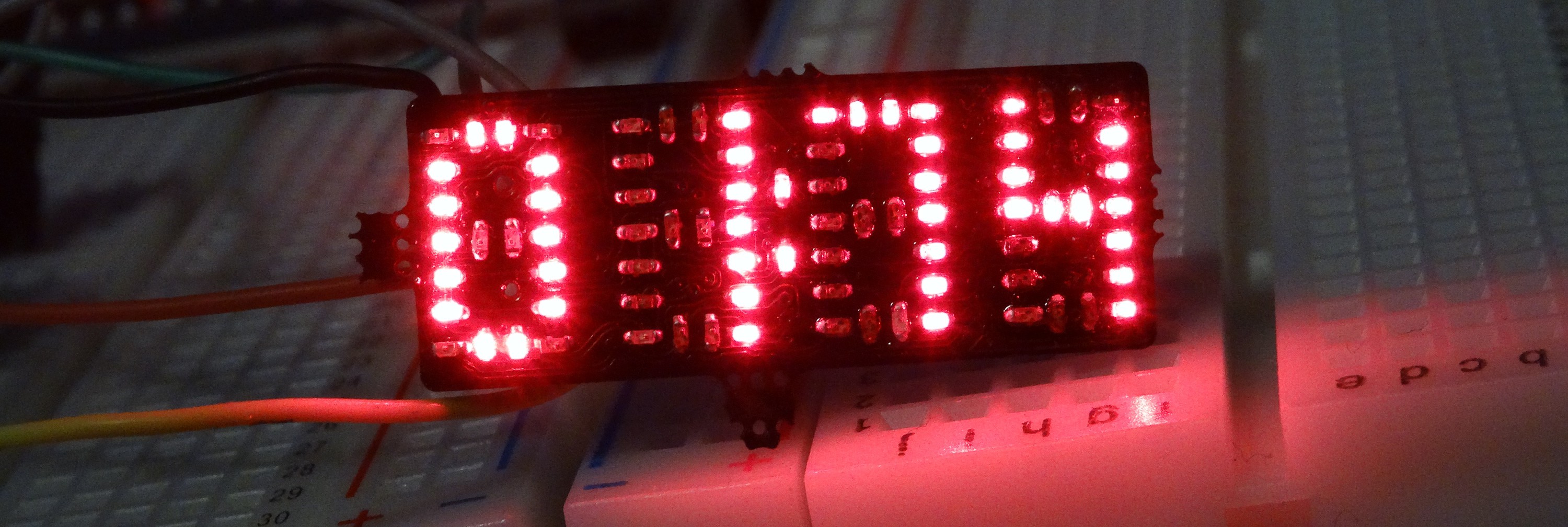
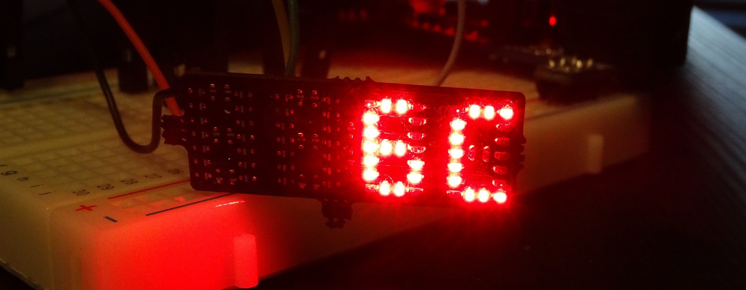
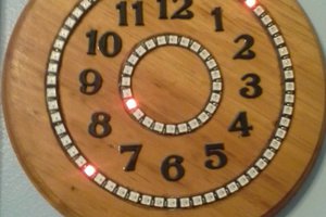
AlexWhile working on #reDOT and #PICTIL I had the Idea of a single PCB LED-Clock. So I came up with reClock. Looking at the LEDs you can see four digits arranged lie in the TIL355-style also used in the #PICTIL project.
Overview
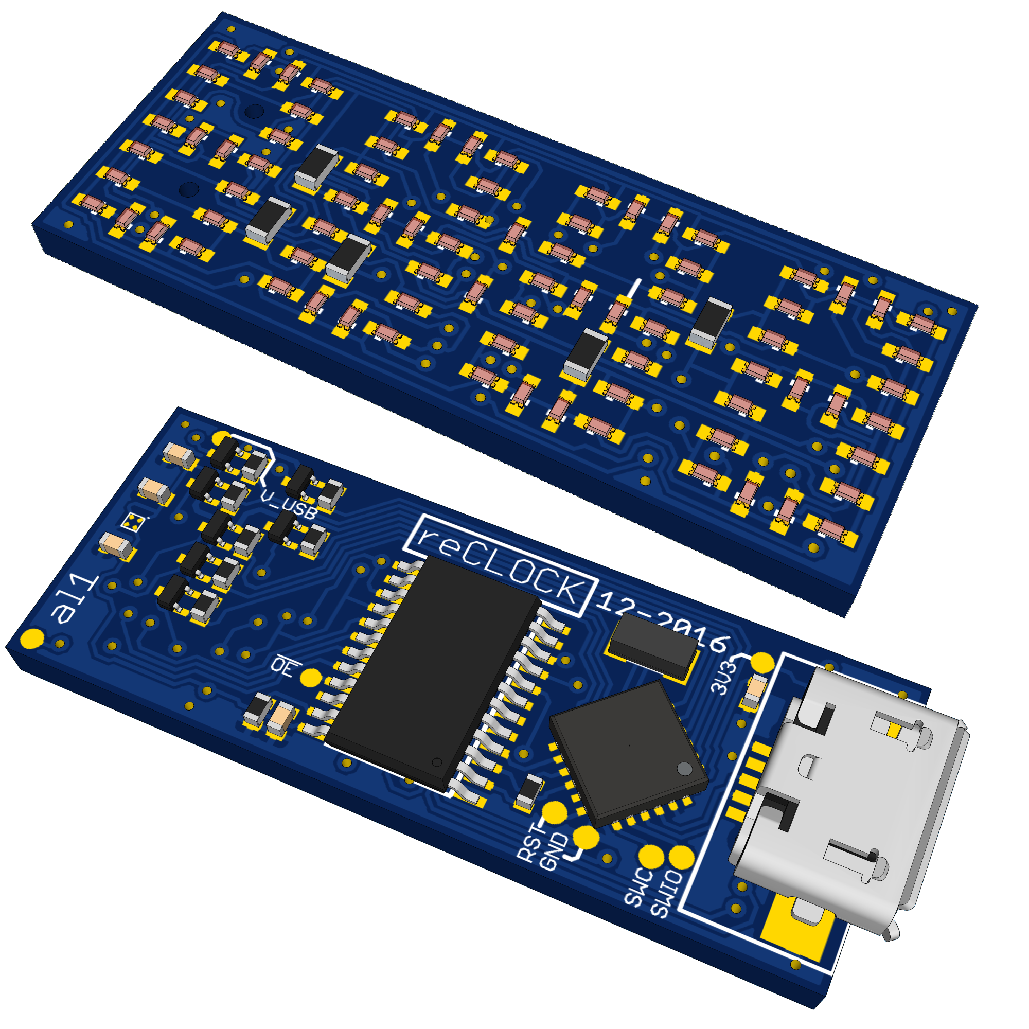
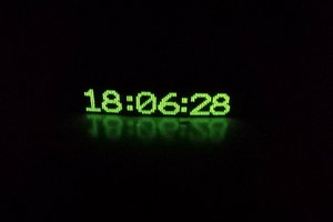
- four digit TIL311-style LED display with dots for a clock
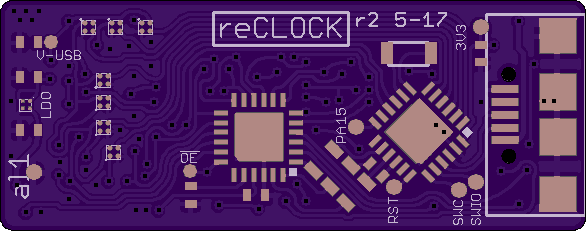
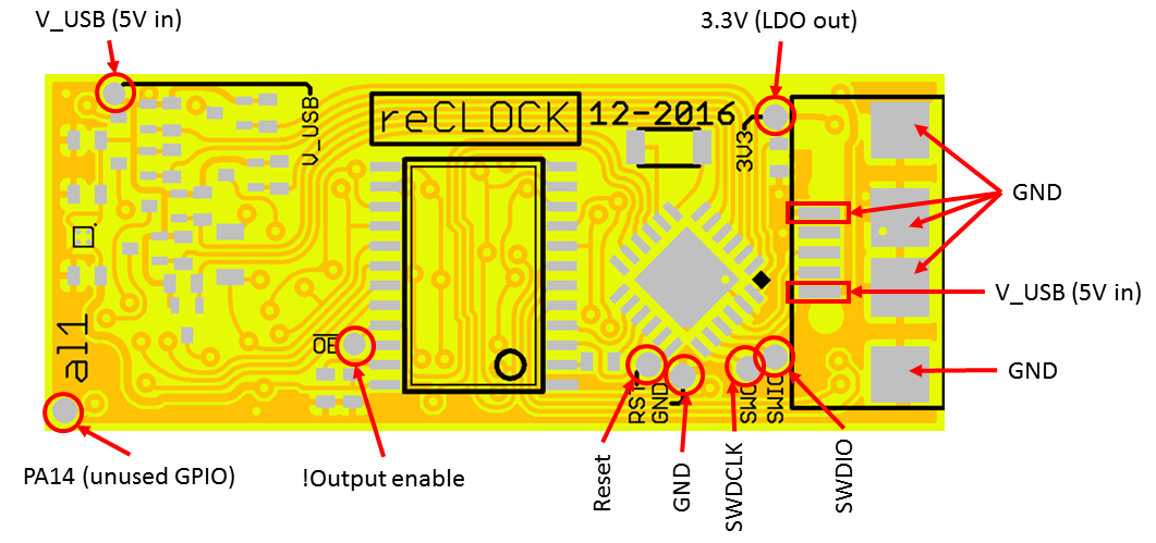
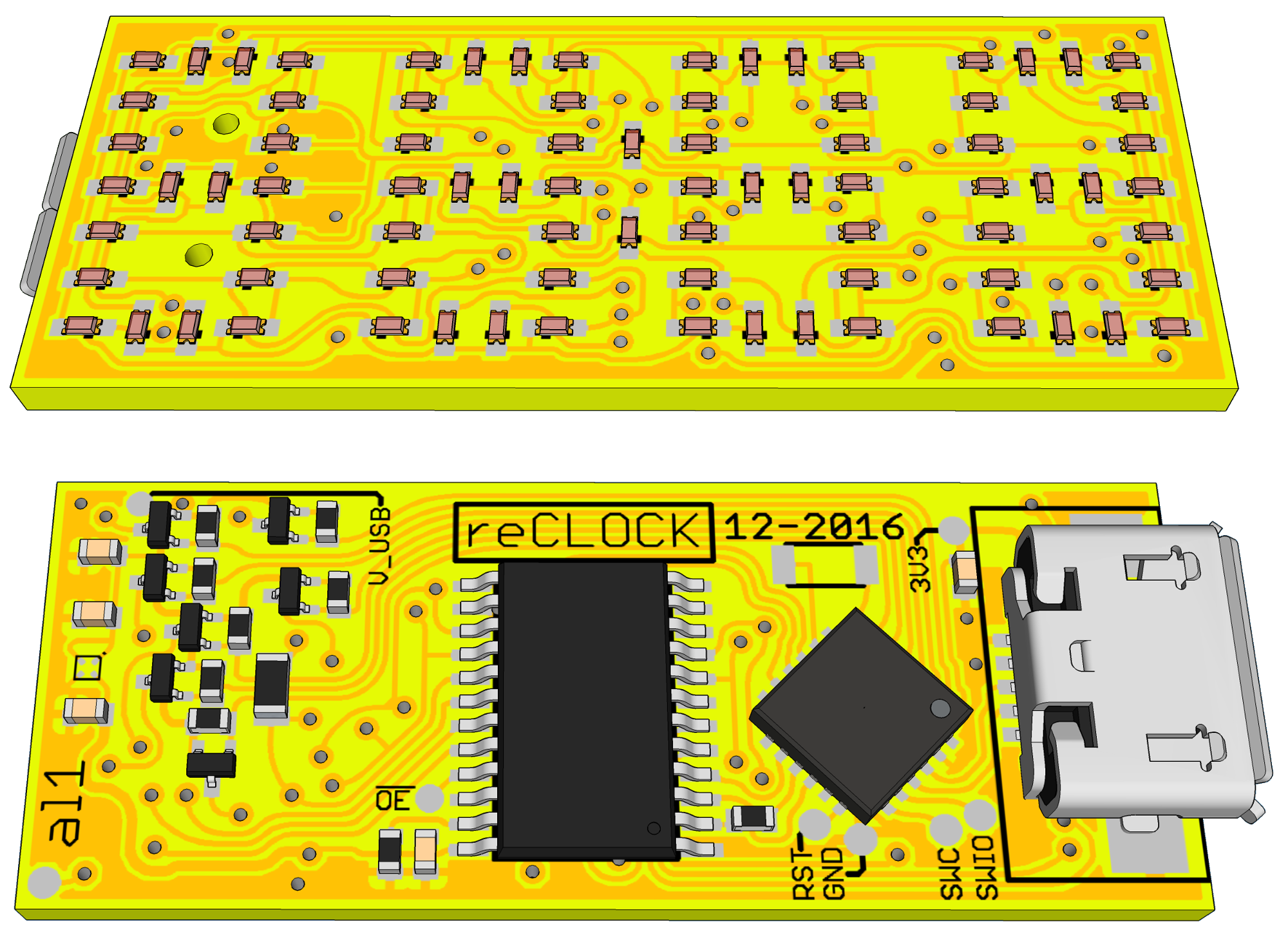
- USB connector on the Back (as power connector an for synchronisation / programing)
- controlled by modern ARM Cortex M0+ Microcontroller (Atmel SAMD09 (no USB) or SAMD11 (USB) )
- RTC integrated into Microcontroller
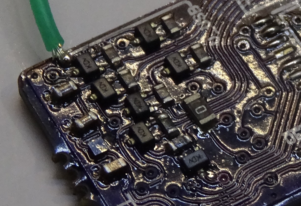
- LEDs controlled with 16-Bit constant current sink shift Register (columns) and seven high side drivers for the rows.
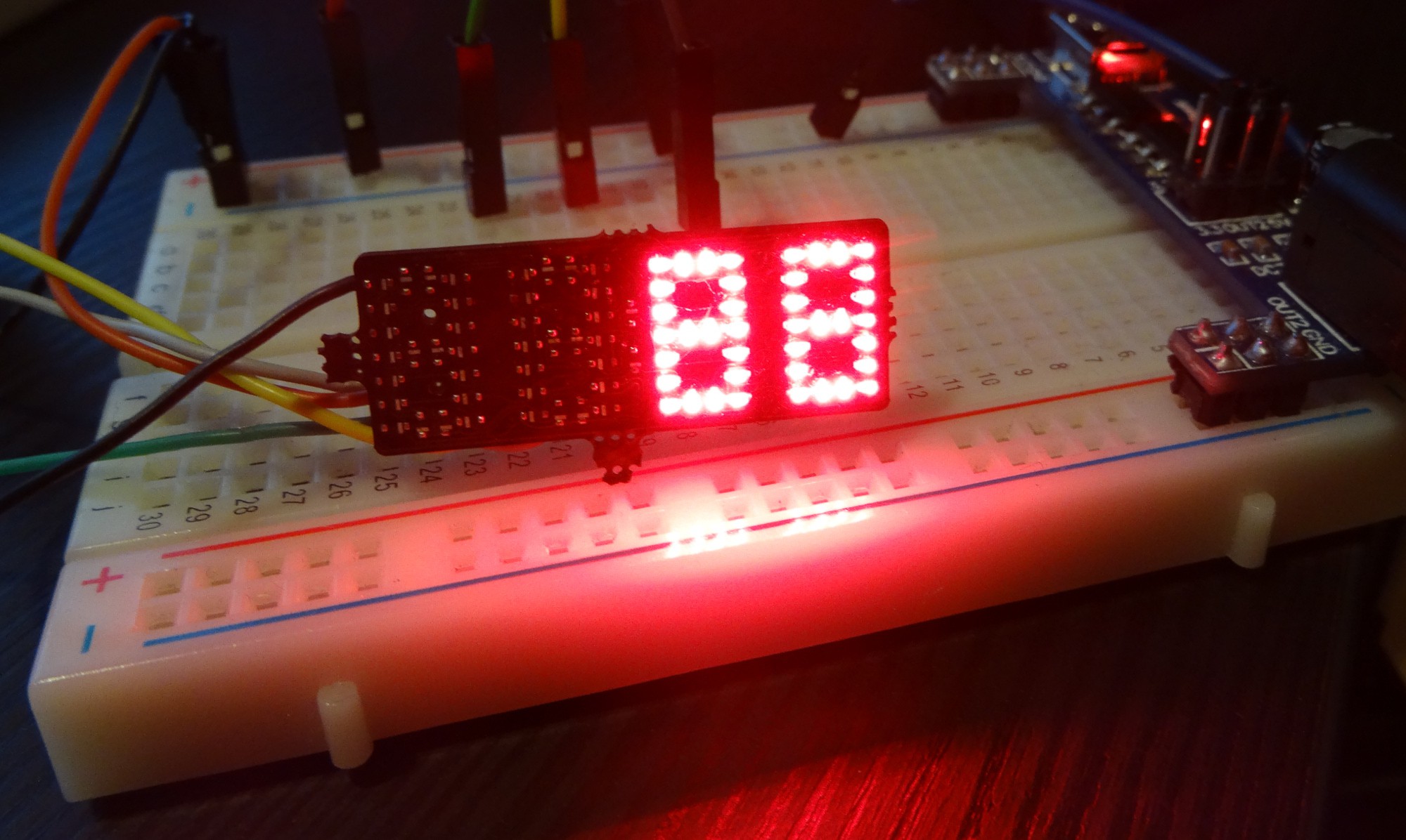
Intended as small clock on display frames, controlled and powered from PC. Clock gets synchronised to PC clock trough some software during starting up the PC and runs than on by using the Microcontroller's integrated real time clock.
More details coming probably soon....
Hardware - System
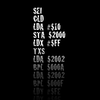
A block diagram does say more than words... (even when it is hand drawn/written)

Software
Till now only an early test firmware is available. I will push the software from time to time to Github (see link on the right)
Credits:
This was hugely inspired by:
#DYPLED by @Yann Guidon / YGDES and
#4 digit charlieplexed segment display by @bobricius
Notes/Ideas for next revision / Errata
- The p-fet circuit is not working if V_USB>3,3V Fix: Power everything with 3.3V
- Use more clearance around testpads and use bigger ones
- Use lowside drive in QFN package
- Update P-Fet Type (DFN style ones like TI's nano-Fets)
- Include some battery backup circuit. (min two diodes for simple battery backup on VCC of MCU and increase normal suppy to 3.6V) Use free GPIO for VCC sense


 Jakub Laník
 Jan
Jan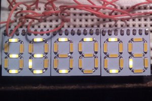
 Yann Guidon / YGDES
some green leds on a flexible board, embedded in your arm would make a nice cosplay gadget ;) what was the name of that Justin Timberlake movie? :D great stuff!