Nick Sayer
GPS is intended primarily as a source of accurate positioning information, but it works by using highly accurate time information. That time information can be used on its own as a side benefit. The accuracy possible depends largely on how good your reception is, but by using GPS receivers with different optimizations in their firmware, you can sacrifice some of the positional utility to obtain phenomenal timing accuracy. Most timing receivers perform what's called a survey, where they will average position fixes over a relatively long period. Once the survey is complete, they will operate in a mode where they presume that their position is fixed. With that presumption in place, they can obtain very good timing results with as few as a single visible satellite - a result that would not be possible had the position not been established beforehand.
As for the accuracy that is possible, it can be as good as on the order of 1 ns or so. NTP running on a Unix computer serving network time over Ethernet isn't going to be capable of maintaining accuracy even 3 orders of magnitude coarser than that, so we can gloss over some of the finer points, but in essence, a GPS receiver has two outputs that indicate the time of day: a serial NMEA sentence stream and a PPS (pulse per second) output. The two work together to communicate accurate time to the host.
The NMEA sentences carry with them an expression of time that is in principle granular down to the millisecond, but in practice it is almost never possible to obtain results that good. For one thing, the NMEA sentences almost never contain sub-second values other than zero, and even if they did, there's no indication within the serial stream what the synchronizing element is. There's no particular edge (such as the initial falling edge of the first start bit) which is deemed the mark against which the rest of the stream describes the time. No, the NMEA sentence will generally tell you what second is currently being described, but you can't generally tell where you are within that second by looking at the NMEA data alone (as a footnote, I'll note that the latency of the NMEA sentence data can sometimes be observed and calibrated and thus you can obtain some level of accuracy from it, but that latency can vary wildly between different receivers and is sometimes not at all stable even on a single receiver).
It is the PPS signal that can deliver the full accuracy available from GPS. Most often, the PPS signal is an active-high signal, whose leading (rising) edge is synchronized to GPS time - marking the start of the GPS second. We are going to concern ourselves here with the SkyTraq Venus838LPx-T timing GPS module. Like most GPS modules, internally it is driven by a microcontroller that generates all of the outputs, including the PPS. The microcontroller is itself driven by a clock, but the clock is not itself generally derived from a particularly stable or accurate source (at least by the standards of accuracy we're talking about here). What winds up happening is that there will be quantization error on the PPS output, since the edge of the PPS signal will be by necessity phase locked with the controller clock, but that clock has no relationship at all with GPS time. SkyTraq chose a clock frequency that's fractional to attempt to insure that there is less likely to be any affinity between the two, and thus the quantization error forms a chaotic randomization inside of a roughly ±6 ns corridor. The good news for those concerned with accuracy is that the module knows the magnitude of this quantization error and will report it in an NMEA extension sentence. Those concerned with maximum accuracy can apply the correction to the observed phase difference of the PPS signal when compared to a reference and obtain a resulting accuracy perhaps as good as ±1 ns or so, at least over short measurement intervals.
The quantization error correction is merely of academic interest for us. Even ±6 ns...
Read more »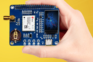
 AlfredC