 jaromir.sukuba
I managed to obtain two samples of fiber - first one is plastic optic fiber (POF) with outer diameter of 0,8mm. This is cheap OF used for home multimedia equipment. Another one is "proper" multimode telecommunication OF, with outer diameter of 250um and core diameter 50um. Here you can see both fibers:
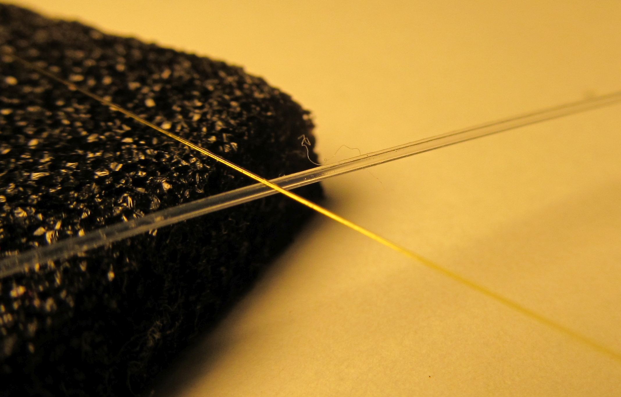
I started my experiments with POF, as it's easier to get some light into it.
I took high-efficiency red LED and by simply holding the end of fiber in front of working LED, I got enough light to see bright red dot on other side of fiber. So, with help of heatshrink tube, piece of wire insulation and piece of metal tube (actually 10mm metal spacer) I made simple contraption to squeeze some light into POF.
The light transfer efficiency is actually very low, I assume it's in order of few percent maximally, but it's both cheap and sufficient for quick and dirty project.
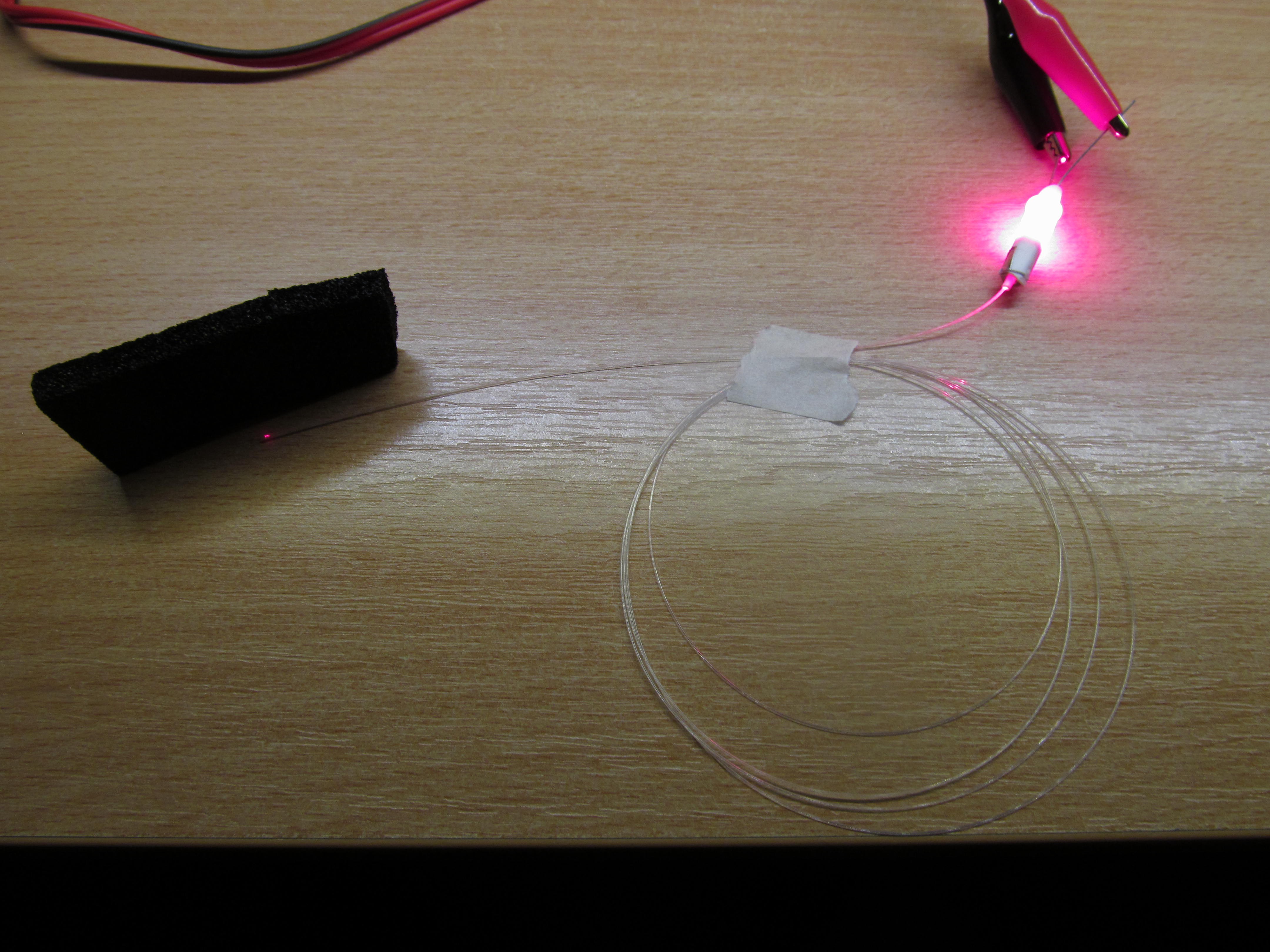
Then, I made one turn on the fiber, to introduce some bend-induced loss. Notice how the bend leaks light meant to be kept inside the fiber.
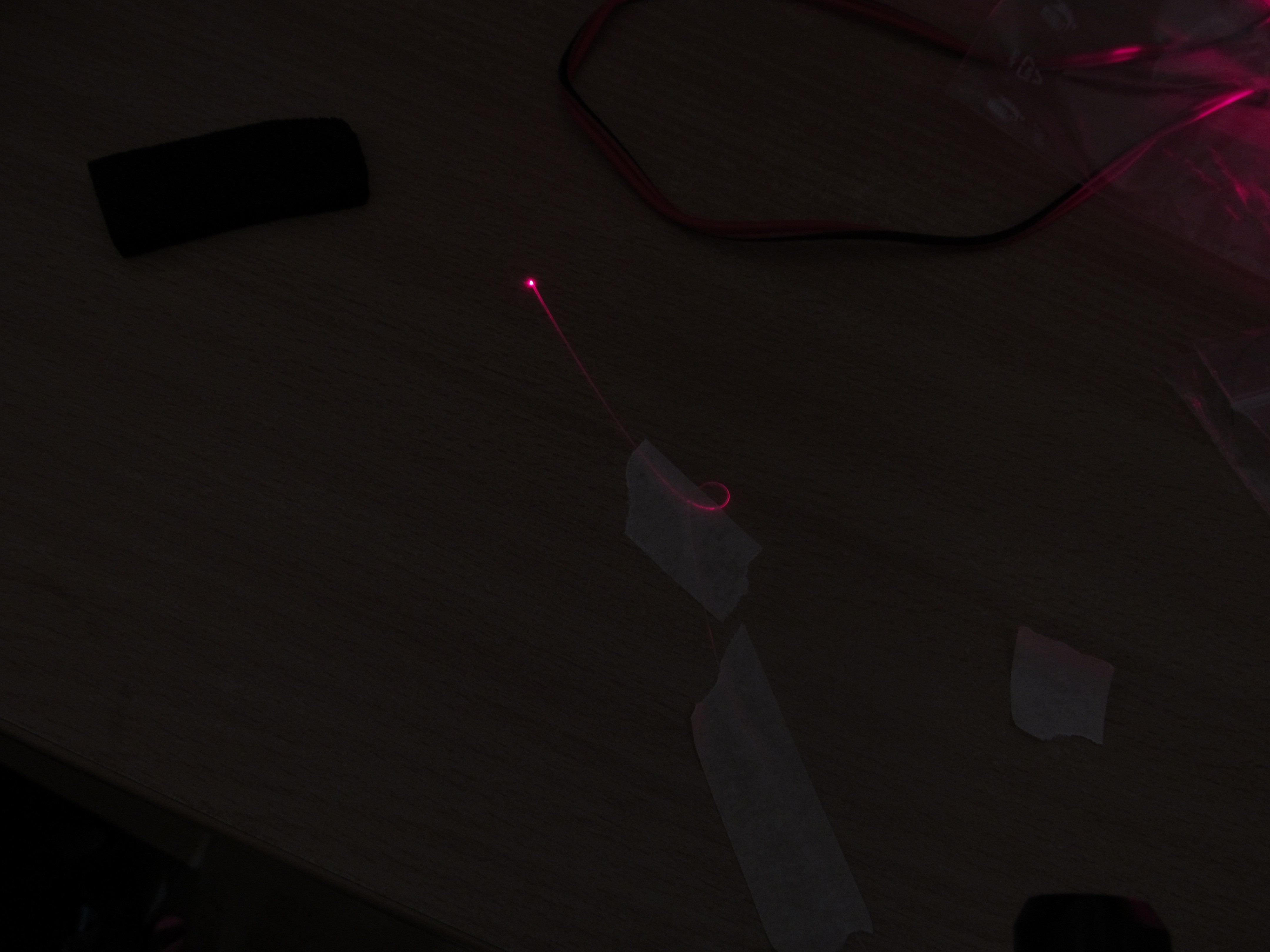
I tightened the bend - at the same exposure, bend is somehow brighter.
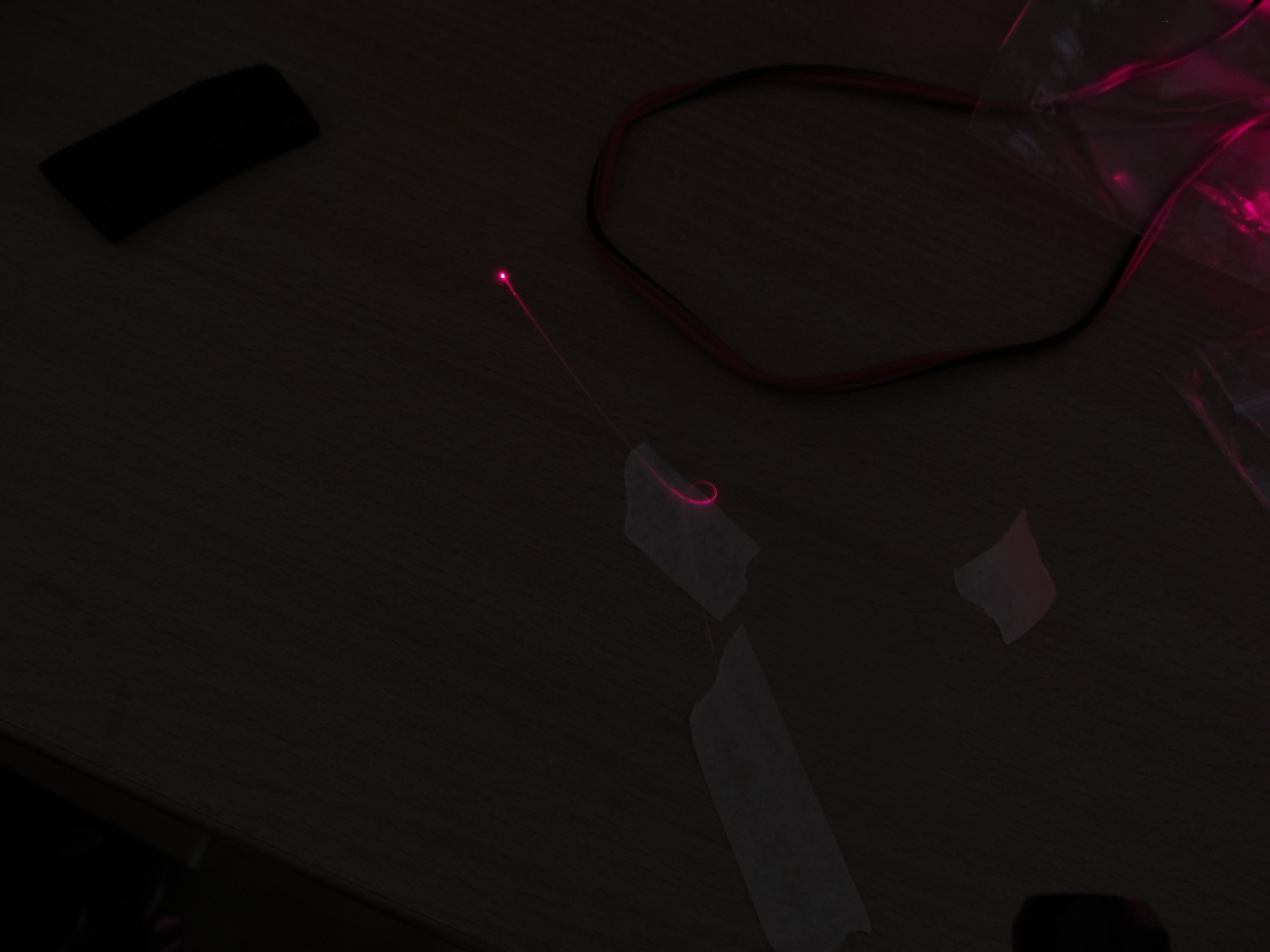
I did some more tightening, the bend is even brighter now.
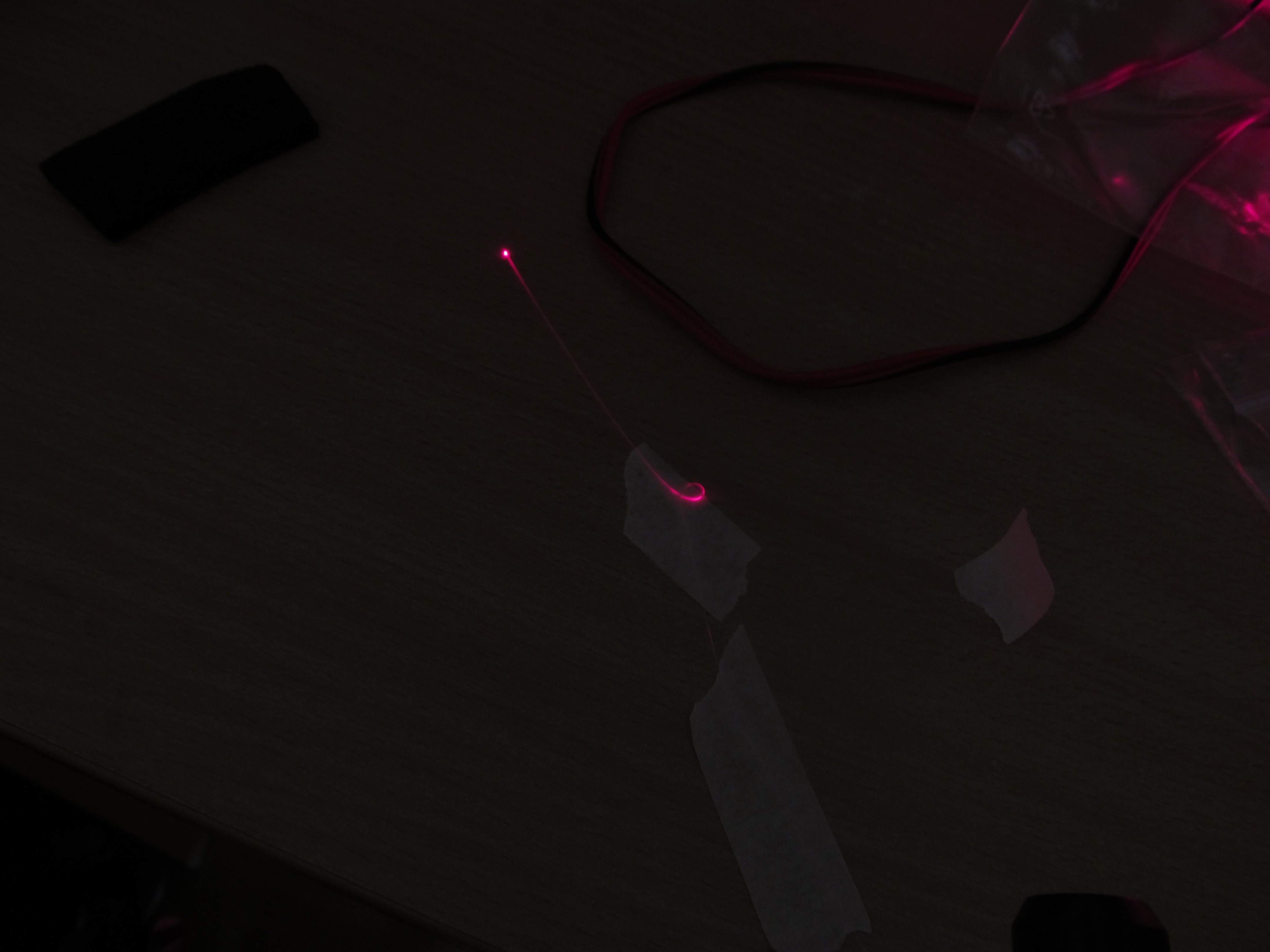
The decrease of outcoming light isn't much visible on photos, despite the exposure time being the same for all three photos; dynamic range on those photographs is probably too high for my camera.
After this foreplay with POF and visible light, I opted to use more common combination - IR light and multimode fiber. The core of fiber is much smaller than that of POF, so aiming the light from LED is not as much trivial as for POF. In professional applications, lasers and collimators/lenses are used, but making this in DIY somehow complicated; buying them is roughly one order of magnitude more expensive than this complete project - so I opted for absolutely barabaric approach; basically the same as for POF - placing open end of fiber in front of IR emitter and hoping for the best.

In this case, 'the best' is coupling ratio at least two orders of magnitude worse than for POF. In order to point the fiber to the emitter somehow more precisely, I inserted the fiber into tubing pulled from 30AWG kapton wire-wrap wire and then again, inserted into another tubing from 0,6mm internal diameter single core wire.
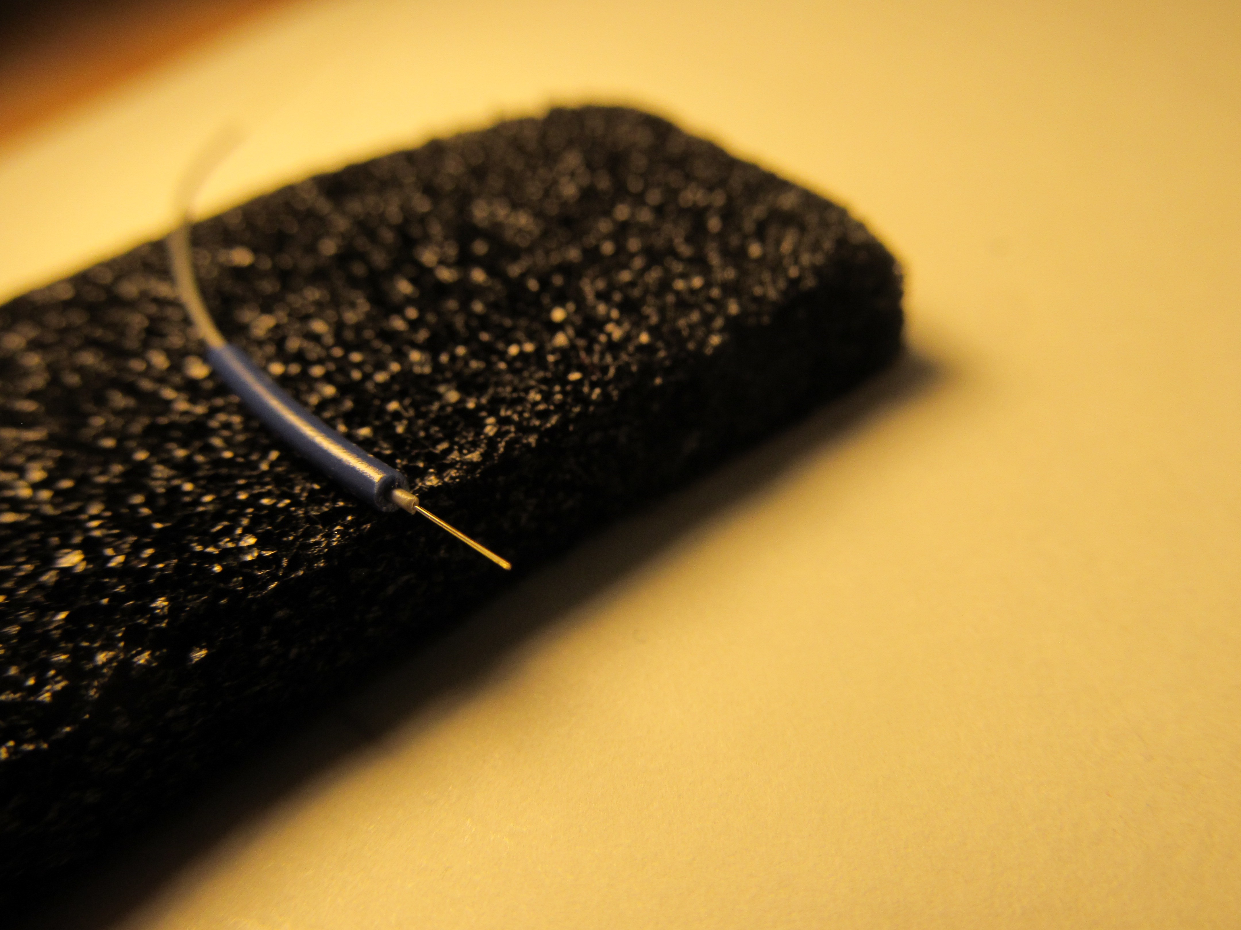
Anybody experienced in fiber optics is probably facepalming/sighing loudly now as this is really medieval. I know there are proper ways of doing fiber termination and coupling to light source, but it's really out of scope of this cheap/quick/simple project.
I inserted the "wide end" of fiber into the metallic tube, touching IR emitter or end of tube and glued it in place with a dab of cyanoacrylate glue.
So, having the fiber somehow coupled to light source, I did the same for photodiode on other side of fiber, forming emitter/receiver couple. I setup my laboratory power supply to source 100mA into IR emitter VSLY5850 and hooked up my most sensitive ammeter to photodiode, namely SFH203. Not surprisingly, short circuit of the photodiode was well under 1uA, somewhere around 50nA. It looks scary, but it isn't that horrible, with little help of opamps and transimpedance amplifiers. With very manageable feedback resistor of 10MOhm, I can get around half a volt on its output, that is easy to process. I took MCP6024 from my junkbox and did quick wiring of two TIAs, followed by voltage amplifiers for a good measure.
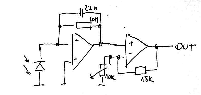
This consumed all four opamps in MCP6024. I added 22nF capacitor in parallel with 10Mohm resistor to decrease bandwidth of the amplifier. It helps to minimize influence of 50Hz hum induced into photodiode circuit. It is possible to decrease its capacitance for higher bandwidth (=allowing to track faster changes of light intensity) if the circuit is electrostatically shielded. Trimmer in second stage allows to change gain (sensitivity) of receiver, I trimmed it to have 2,4V of full output, in order to fit the input range of particular ADC I used, as described in future project logs. Output of this amplifier is is now tracking the insertion loss in fiber, falling to two thirds of initial value after slightly squeezing the fiber with my fingernail against finger, returning back to original value after release. That is good base for my sensor.
All in all, I had to use somehow brutal method of fiber coupling and higher gain in TIA after photodiode, but this was balanced by saving for proper fiber coupled laser diode (usually three digit figure in USD). I made four of such couples, with fairly reproducible results and zero scrap.
Discussions
Become a Hackaday.io Member
Create an account to leave a comment. Already have an account? Log In.