 Tim Wilkinson
The 8BitRobots module consists of the following 6 components:
- Hardware
The Pi Zero is the ideal base for a robot. It's cheap, relatively powerful, runs Linux and comes with WiFi and Bluetooth. Add to it the RoBonnet, my Pi Bonnet which includes PWM outputs (servos and ESCs), an H-bridge (motors), TTL serial (expansion), I2C output (more expansion), encoder inputs (RPM), pressure/temperature sensor (altitude), IMU (orientation), power monitor (battery management), and DC power regulator (lots of different battery options). The result is everything needed for a bunch of different robots. - Software
To manage everything, there's a Javascript, distributed robot platform running on the Pi. A robot can be made one or many Pis. This software binds them together into a single, simple, robot API (https://gitlab.com/8BitRobots). - Programming
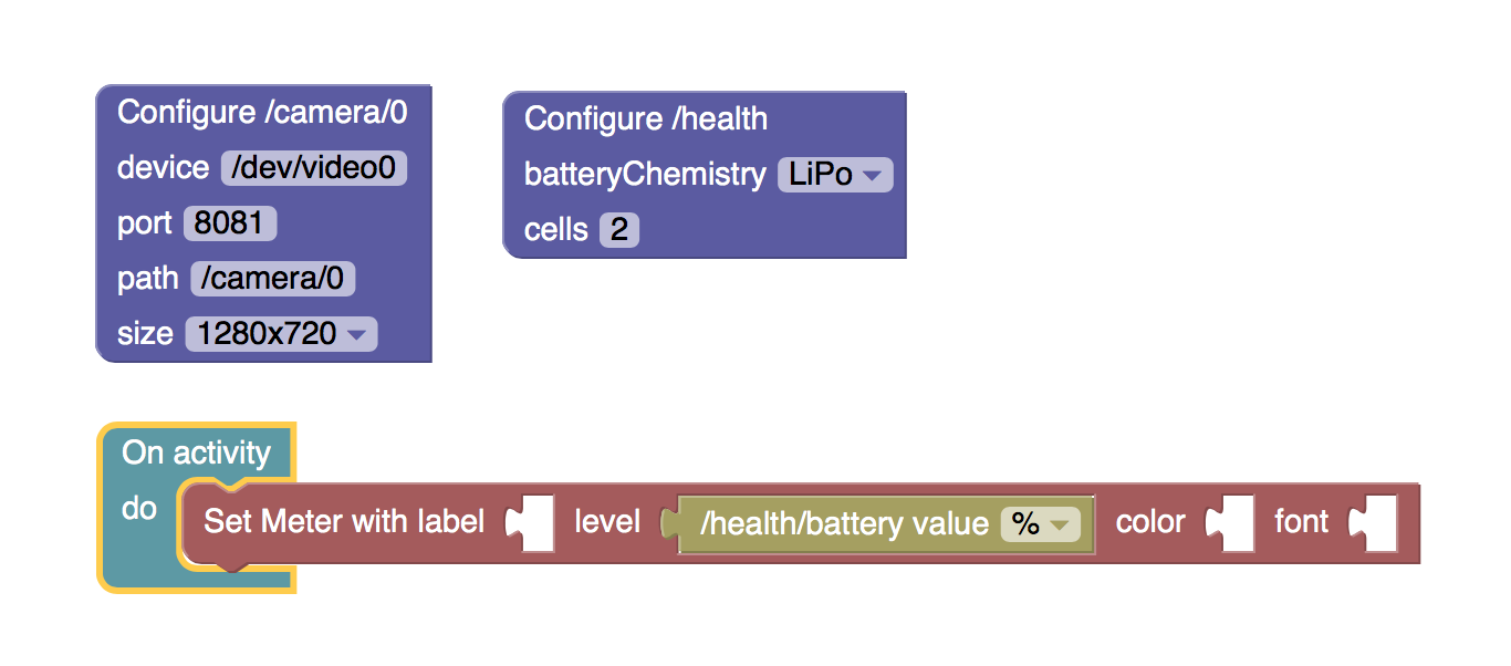
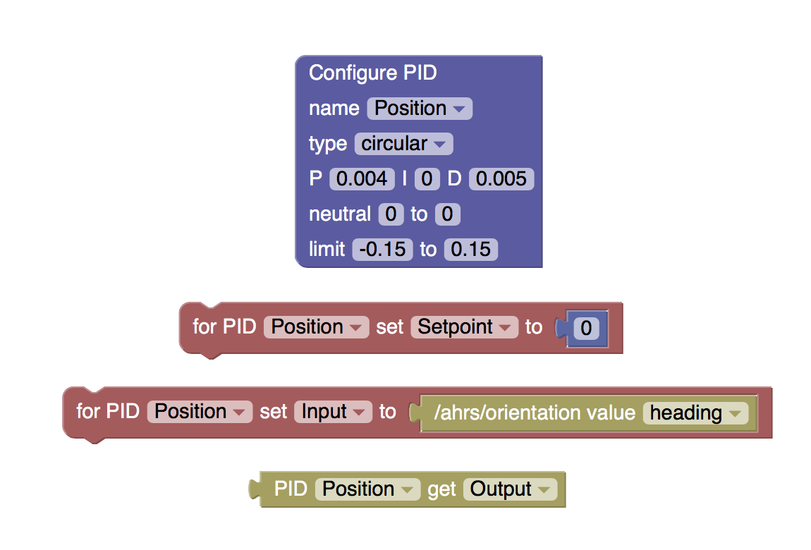
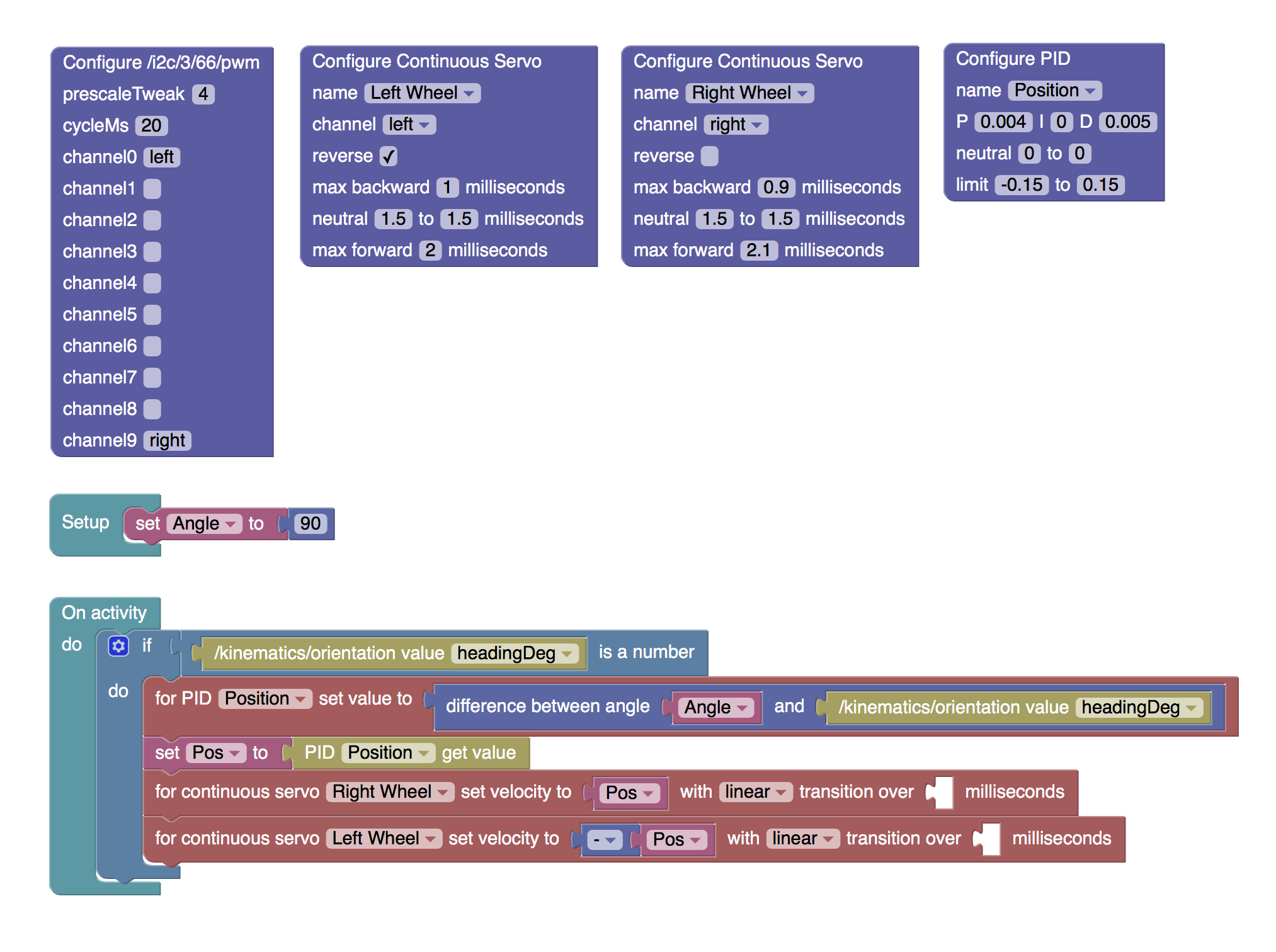
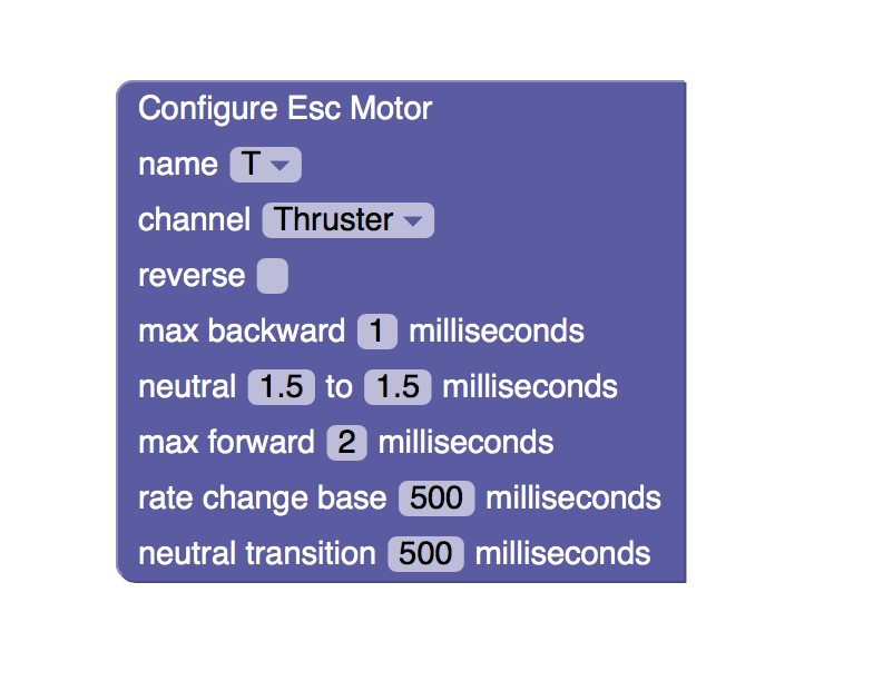
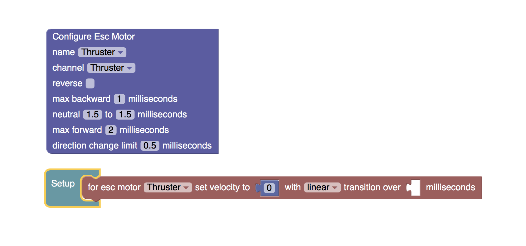
You can write your robot in Javascript, but it's easier to write it in Blockly. Blockly (from Google) is a Scratch like graphical programming language. Here it's been adapted to create robots. It runs in a web browser and makes it easy to turn a bunch of hardware into something much more useful. - Controls
If you've every played with one of those cool Sphero toys, you'll know how good it is to use your mobile phone to control a robot. The same interface ideas are used here, but with a few more tricks to make it configurable for your particular robot's needs. - Installation
If you just want the software to create a robot without learning all about Linux, then everything for an 8BitRobots node is rolled into a custom Linux distribution. Download it onto an SD card, boot, and you're ready to go. - 3D Printing
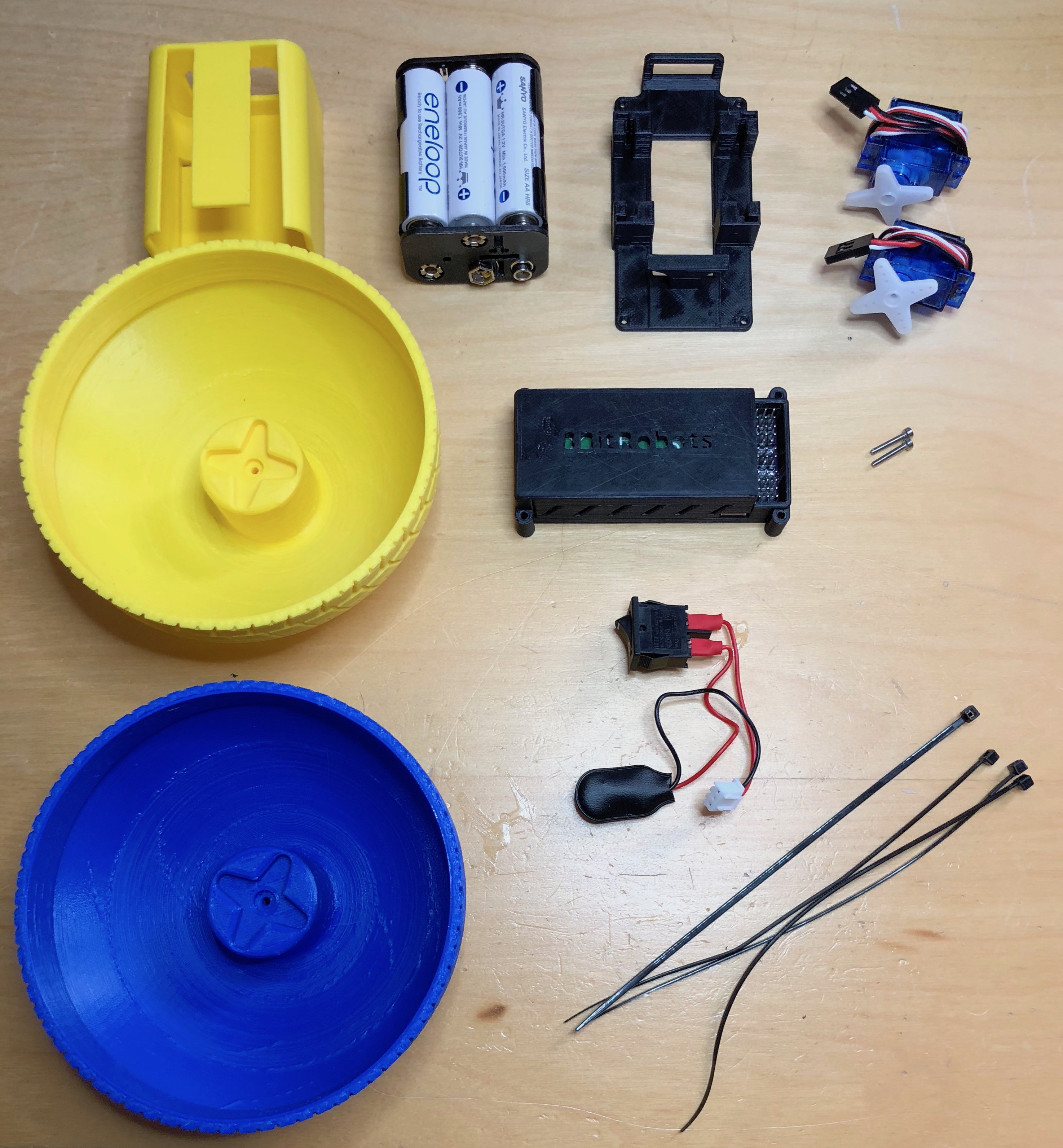
Finally, what's the point of building robot hardware then having nothing to use it with? So there's also a bunch of 3D print-at-home robot projects. Print a few 3d parts at home, combine it with the components above, and build something fun.
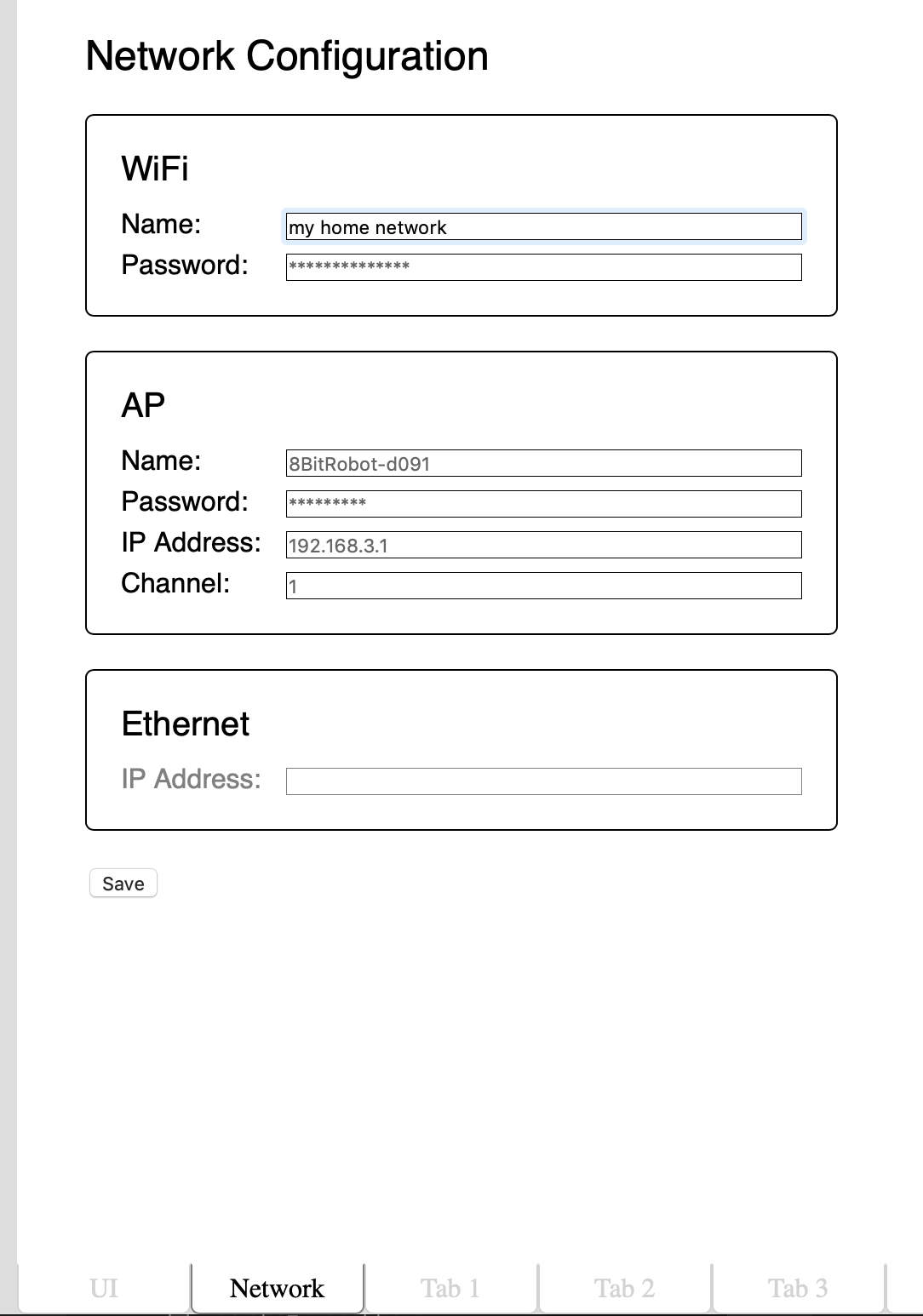 Today, what is probably the last part of the development environment landed; the network configuration tab. Ignoring my excellent visual design skills as demonstrated above, the Network tab allows configuration of the three networks supported by the module:
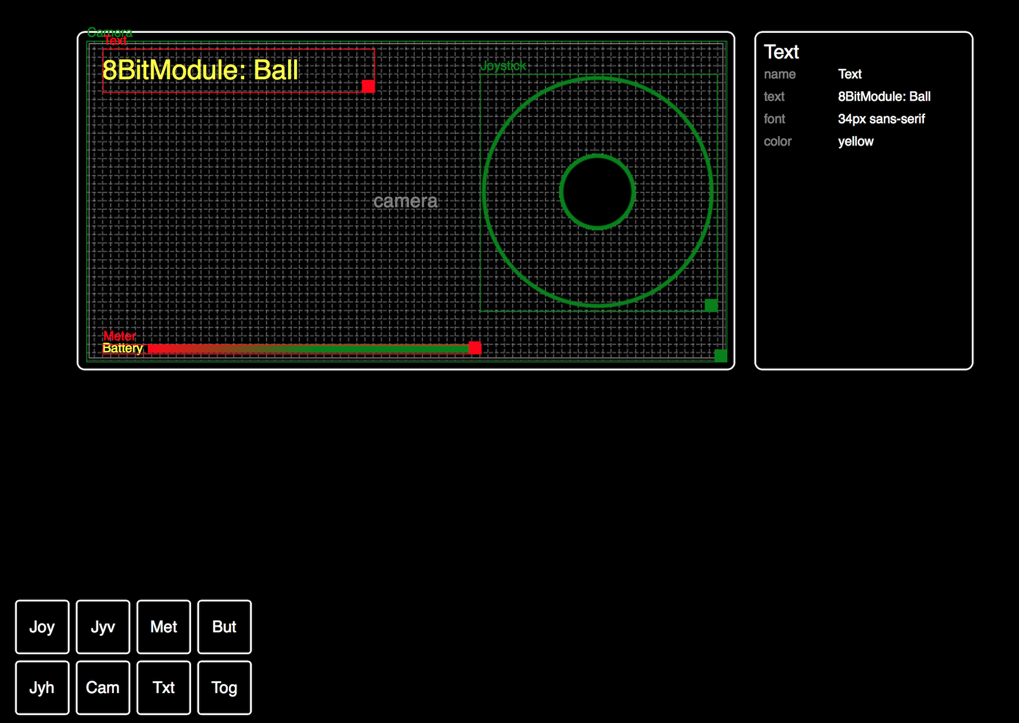 One of the original goals for this project was for robots built using the Module to be controlled by phone using a web browser. However, because each robot is unique, there is no one set of on-screen controls which are ideal for all robots. To address this we need a UI Designer; a tool for developer to drag-and-drop controls onto a virtual screen, and to include just the right controls in just the right places for each robot.
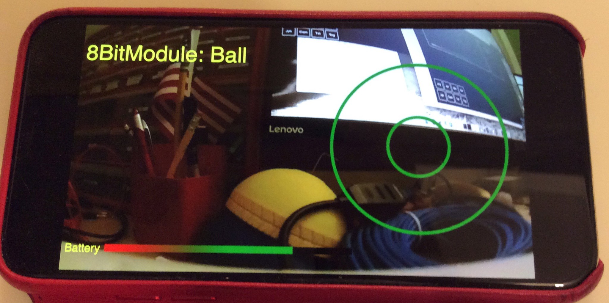
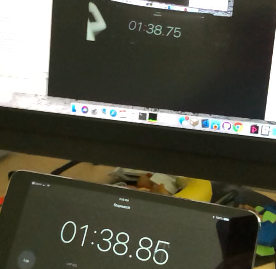 The photo above shows the camera streaming over ethernet (the same software but part of the ROV build - see here
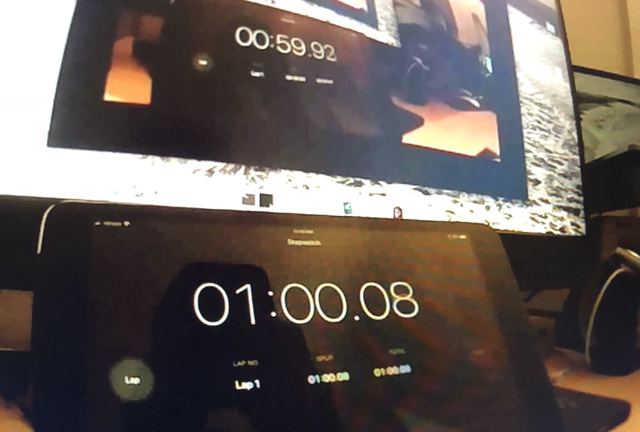
 There are a few key differences:
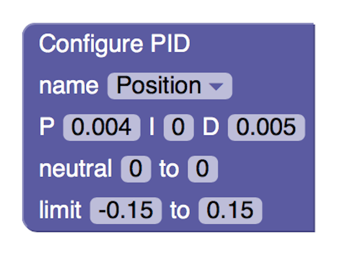

 Joshua Elsdon
 Redtree Robotics
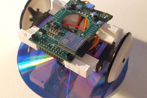
 Krzysztof Pochwała
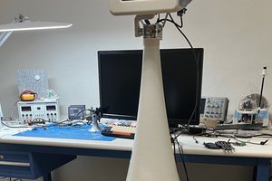
 Apollo Timbers