 Tim Wilkinson
The core to my robots is PWM. This is true for the robot arm (servos), the robot car (ESCs), or the ROV (more ESCs). The Raspberry Pi only has a single PWM output and while you can use software to create a few more, early experiments with this method quickly showed its limitations. My first PWM control board was from Adafruit a long time ago, and I've based all my robot controls on the same solid PCA9685 which provides 16 PWM outputs.
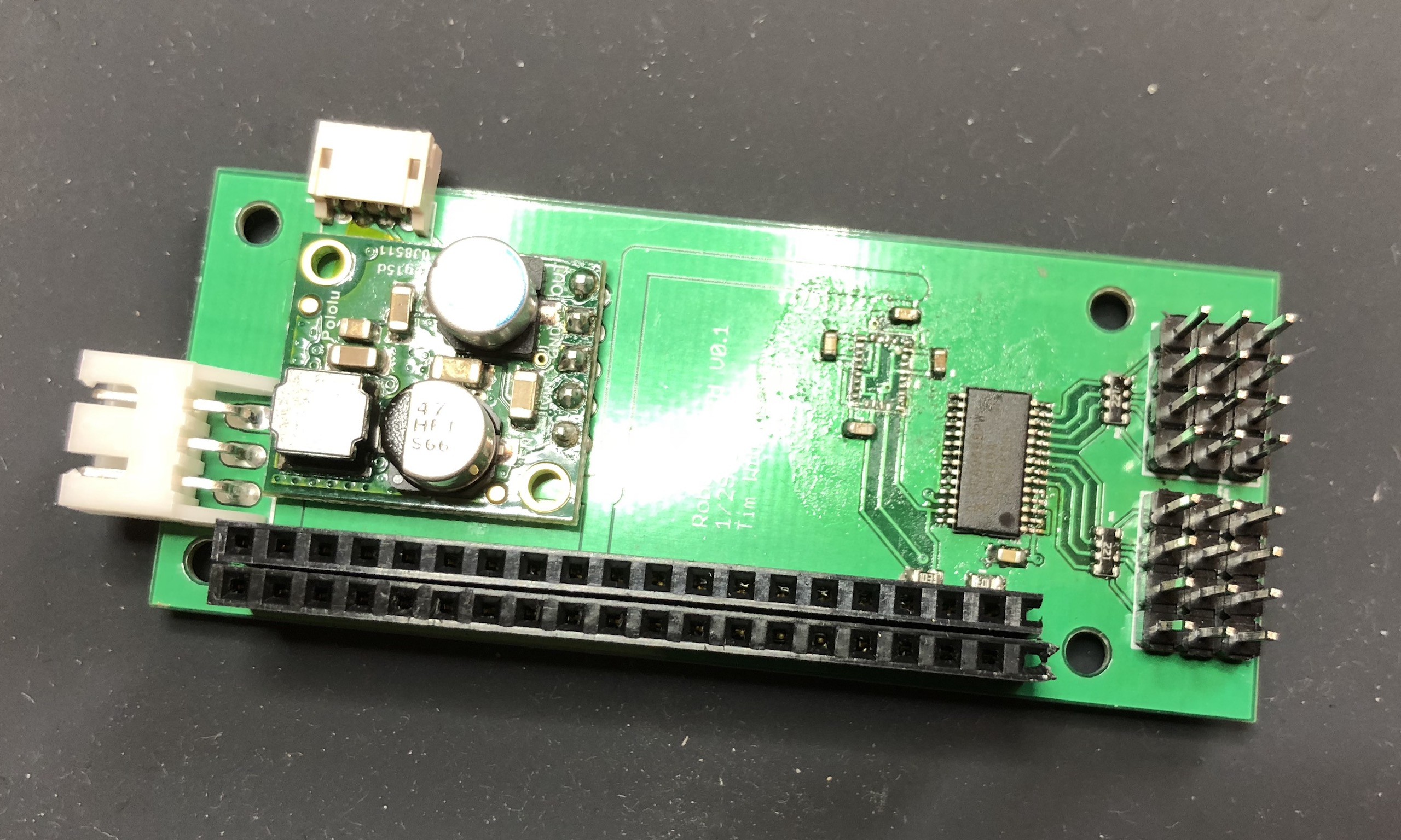
The first version of the RoBonnet (shown above) was a simple test bed for this chip and the basic board form factor (the IMU test to the left of the PCA chip failed - guess I screwed that up). This version brings out 8 of the 16 PWM signals. The Pi plugged face down into the 40-pin connector at the bottom. To the left you see the power input and a pre-purchased power board (from Pololu.com).
Although you can't tell from this picture, the board is longer than the Pi so the PWM pins are accessible, but this version was just a little too short so it partially obstructed some of these pins. I had to make it 2mm longer because, apparently, I can't measure stuff properly.
The power connector on the right was choses to accept the standard plug you find on a 2S LiPo battery (thank you Beagleboard Blue for that idea). The converter turns that into 5V which is used to power the Pi as well as everything else. The final goal is to provide 3A at 5V to the node and attached hardware.
The boards were prototyped using DirtyPCB.com which I've found to be a fantastic, quick turnaround service. Assuming you avoid the Chinese New Year (I didn't) you can go from submission to board-in-hand in a week.
Discussions
Become a Hackaday.io Member
Create an account to leave a comment. Already have an account? Log In.