 Pavel
PavelAs I integrated the ROM into my ECM-16/TTL Pilot-1 cpu, I've encountered a couple of problems:
- there is an intermittent short circuit developing on data bit A line, which makes it stuck to HIGH no matter the actual switch position
- on address E it seems to be no output
- reset signal is not fully implemented, so the address counter won't clear to zero.
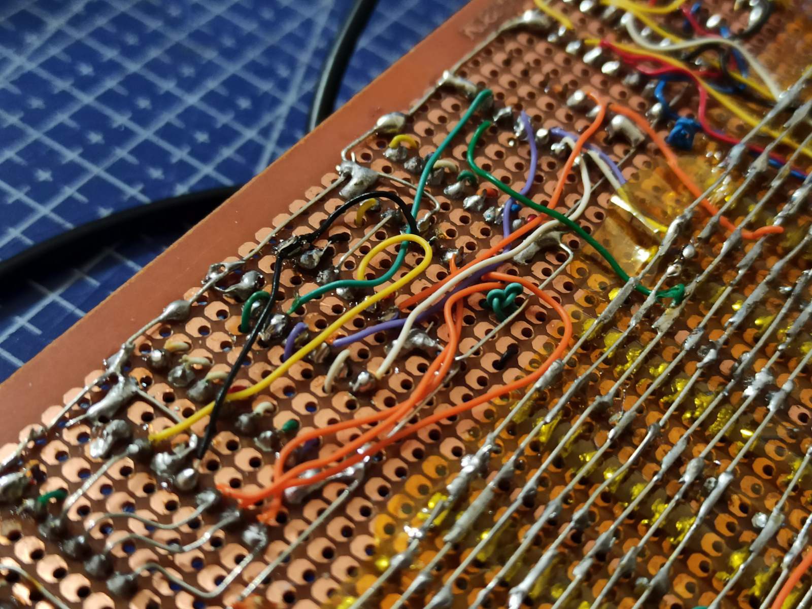
The first two of the above problems were solved by soldering some wires that came loose - as they are quite exposed, they are fairly delicate and were not able to handle stresses of me moving/transporting the board around.
The reset was implemented by small adjustment of board's wiring.
Here is the board's back, and it is visible that its wiring is fairly fragile in places. I intend to apply epoxy to this side of board to make it sturdier and less prone to damage. The downside is that if something happens to the board after that, it would be next to impossible to repair it.
Here is the schematic/model of this ROM module I use in my simulations:
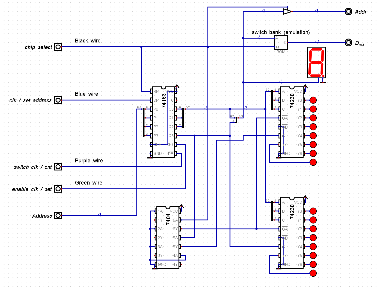
In actual board, the pair of 74hc238 3-to-8 decoders drives address lines of switch bank, activating a single word to the data bus.
Discussions
Become a Hackaday.io Member
Create an account to leave a comment. Already have an account? Log In.