 David Scholten
Super capacitors are ready
I ended up with 12x 100F 2.7V super caps from my local Aztronics store. These things are rated for an "average" current of 30A each with a "peak" current of 60A. This is a total theoretical storage of 4374 joules. I connected them all together in two strings of six to form a 33.3F 16.2V capacitor with a current rating of 60A continuous.
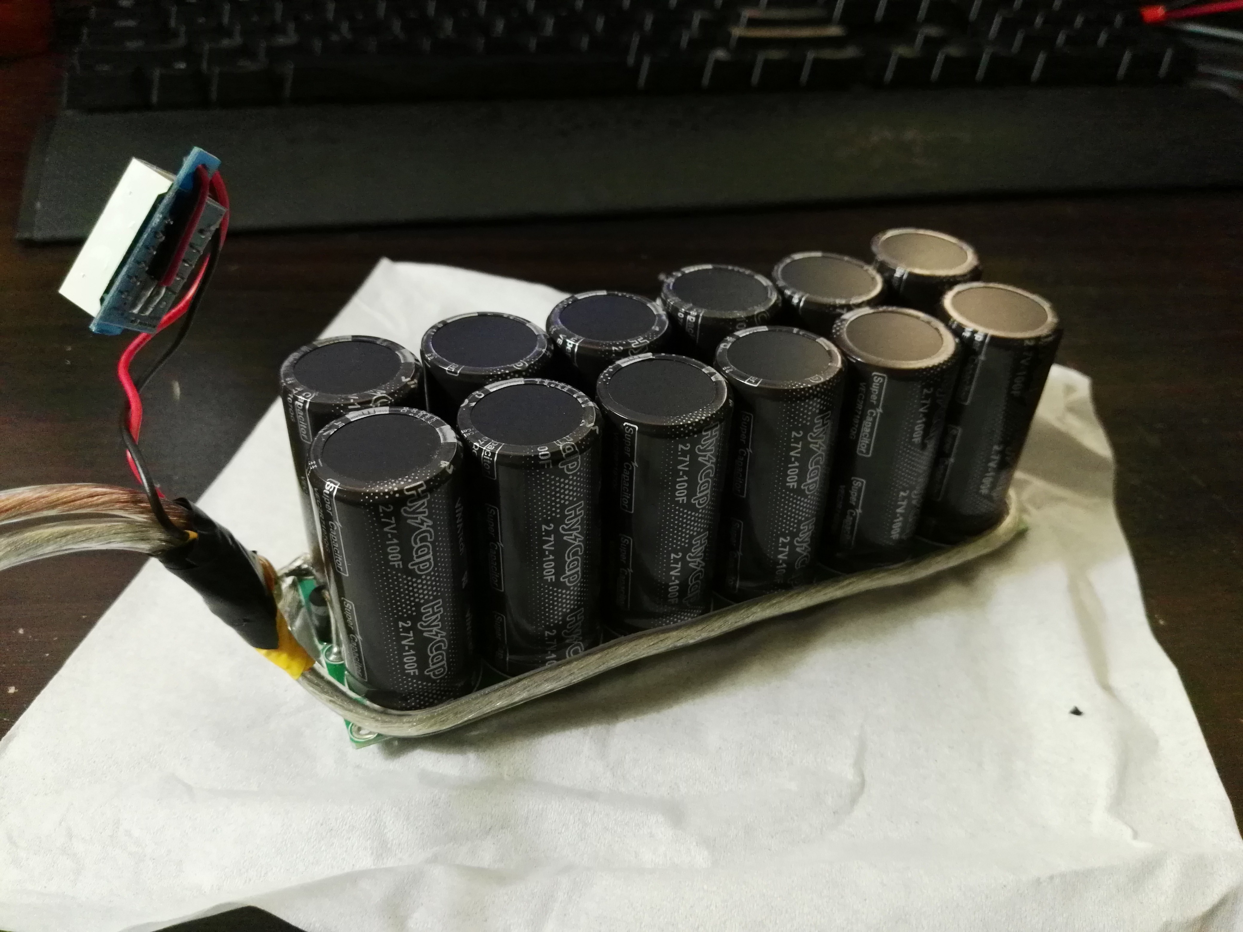
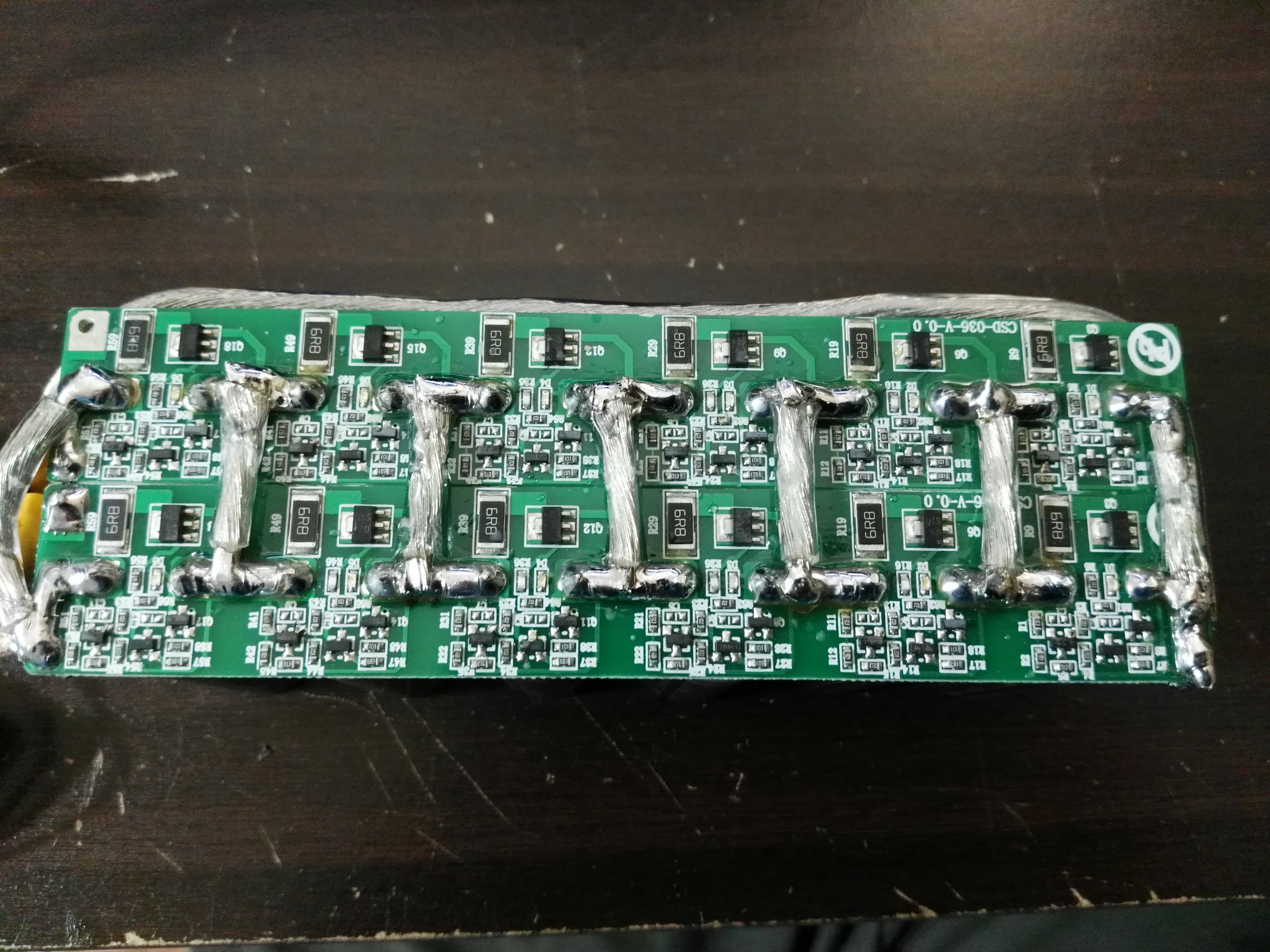
To balance the super capacitors I used two boards that I found on eBay for a reasonable price. Each board will trigger at 2.65V and discharge at just under 0.4A. Importantly though, I connected each capacitor in the two strings in parallel (i.e. the whole thins is now six 200F 2.7V capacitors in series). This allows the balance circuits from each balance board to balance the capacitors from each side. The danger before this change was that if I charge at 800mA and one string takes on more than half the current then a single 400mA balance circuit is inadequate.
Charging Circuit is working
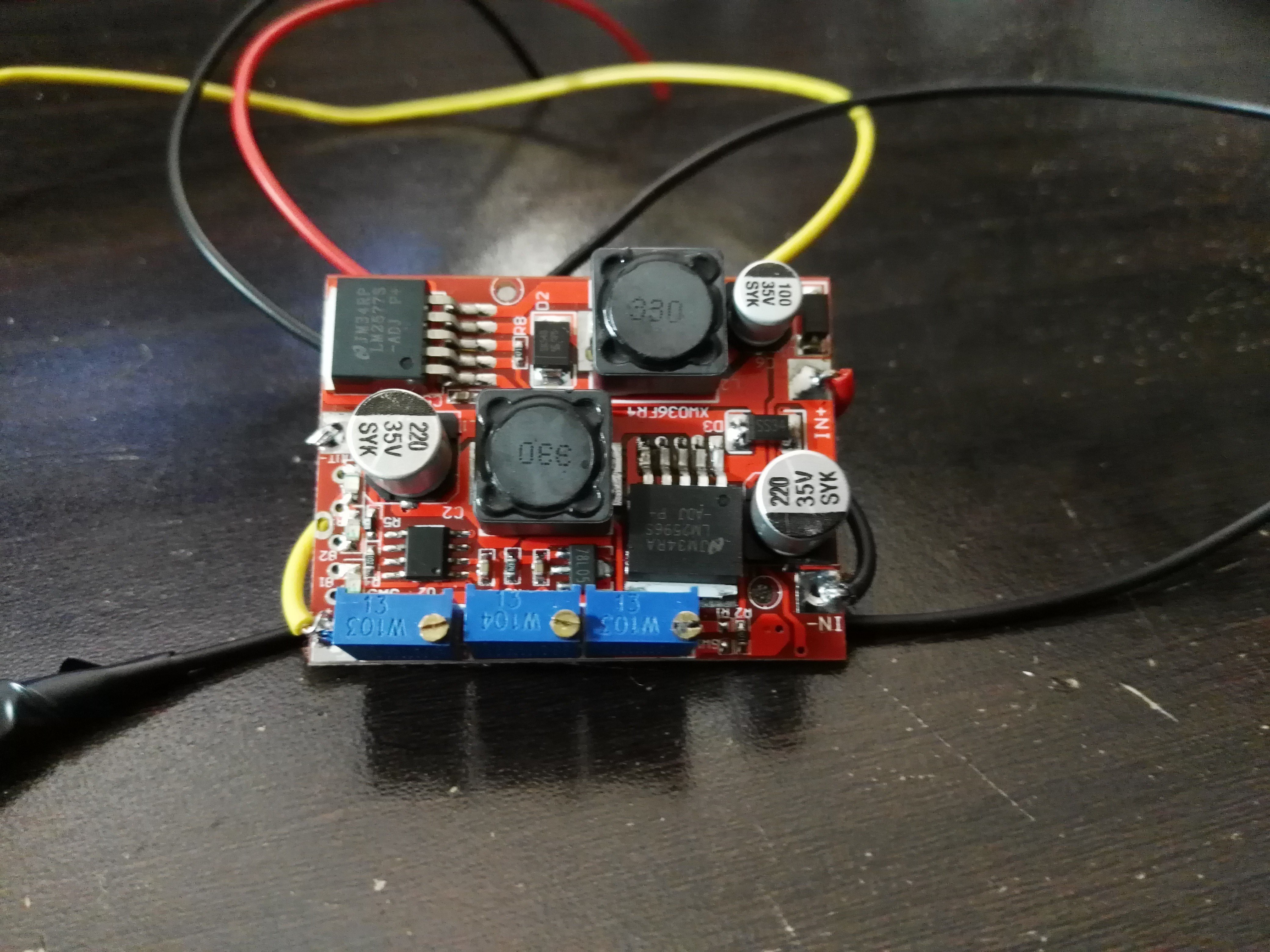
I grabbed a 0-30V to 0-30V boost-buck converter from eBay that is capable of delivering up to 3A to charge the super caps. At that rate it would take 3 minutes to charge the 4374 joule bank, but at the rate that can be safely balanced (0.8A) it will take 11.25 minutes minimum. Frustratingly, I cannot find little boost-buck converters like this that have any maximum power point tracking capability or a "constant power" mode. As the capacitors charge from a constant current the charging power increases proportionally with the capacitor voltage. This means I need to size a battery's power for the charging power needed near the completion of the capacitor charging.
Other equipment that arrived
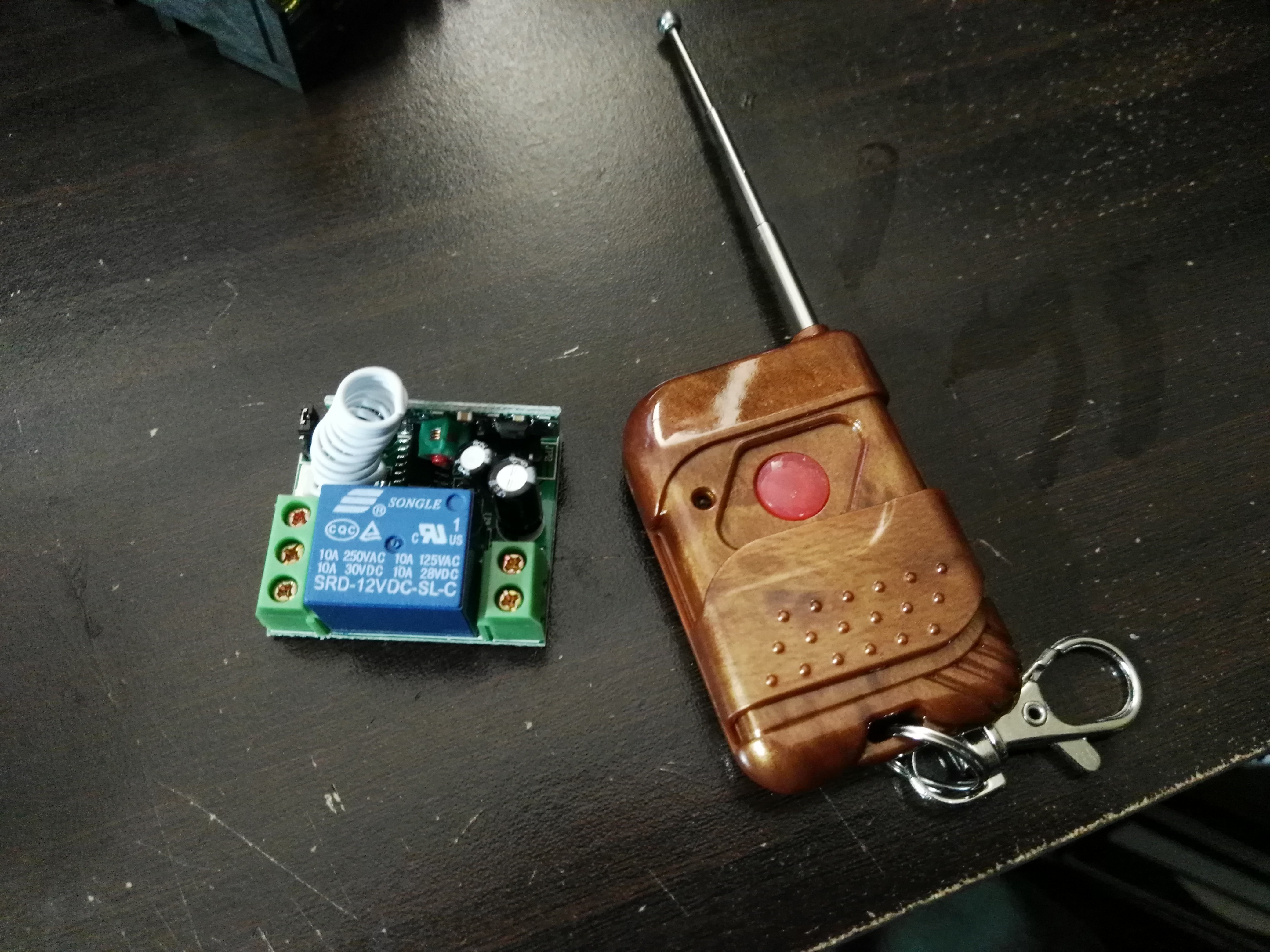
Due to the high currents involved I thought it would be best if a heavy duty relay or two was in charge of switching the output on/off. As this box is supposed to be resilient, it would be best if I only had to replace relays and not mounted switches. These relays from eBay have a footprint I have never before seen and look eerily like vacuum tubes.
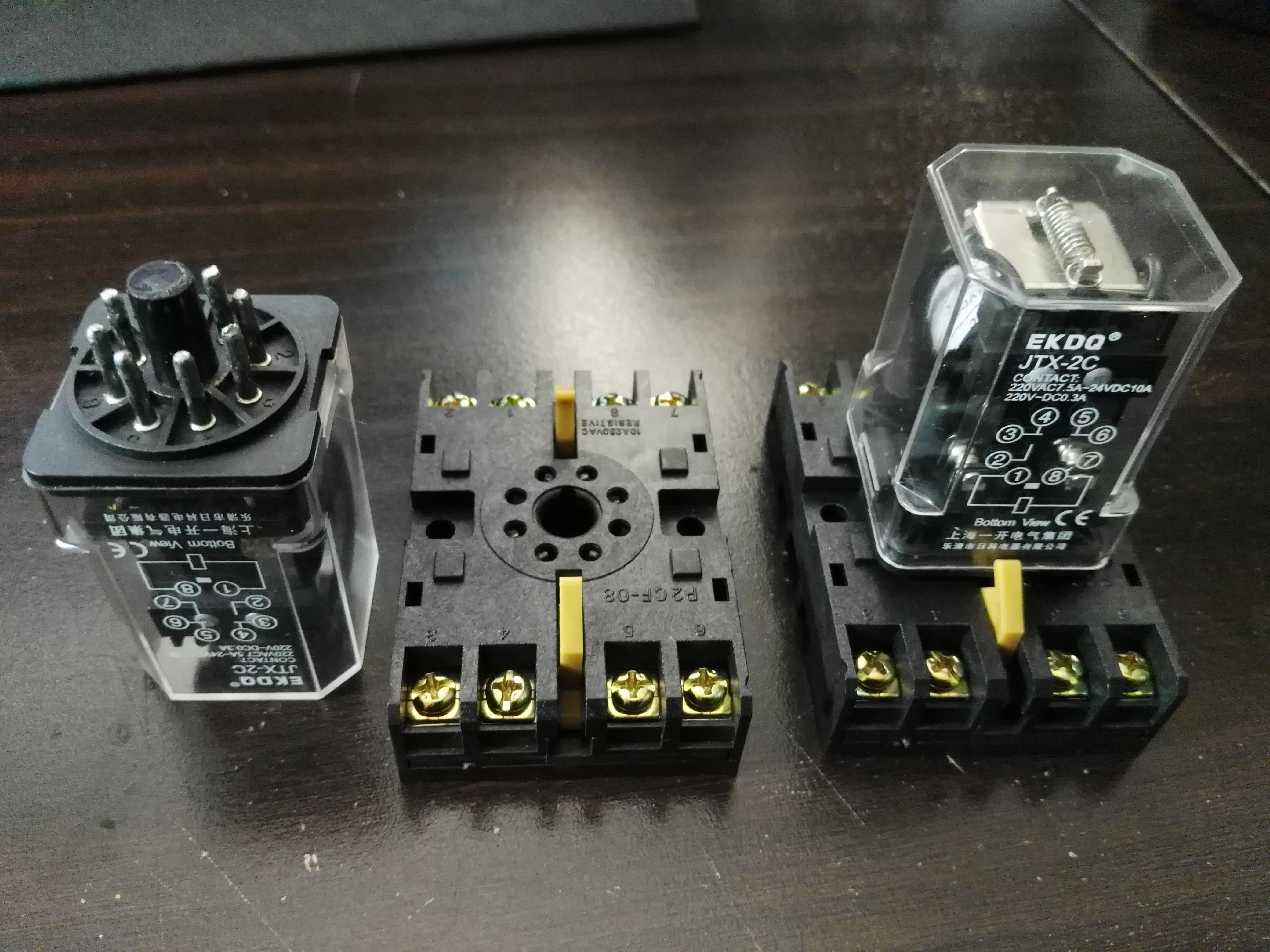
This leads to the next great features of using relays which is controllability. Now I can use standard wireless switches to also power on/off the outputs of the box. This will be VERY useful if I am powering something dangerous in the middle of nowhere (rail gun?) and want to momentarily turn it on from a great distance. This little wireless module can toggle between momentary mode and latch mode.
Next update:
I have ordered 12x 50-100W boost converters from eBay to regulate the output of the super capacitor bank. Boost converters are ESPECIALLY handy when paralleling them as their outputs are through a diode. In addition, if the load is too great then the output voltage basically just drops as the boost converters begin to approximate a single diode. The best part about cheap low powered boost converters in parallel rather than a single high power boost converter is that the cheap ones are overrated and will quickly overheat. This is perfect for a pulsed power application as this means the cheap boost converters will provide more power than they should for their heat dissipation capabilities, but without the chance to overheat due to continuous operation!
Discussions
Become a Hackaday.io Member
Create an account to leave a comment. Already have an account? Log In.