 David Scholten
The boost converters have arrived!
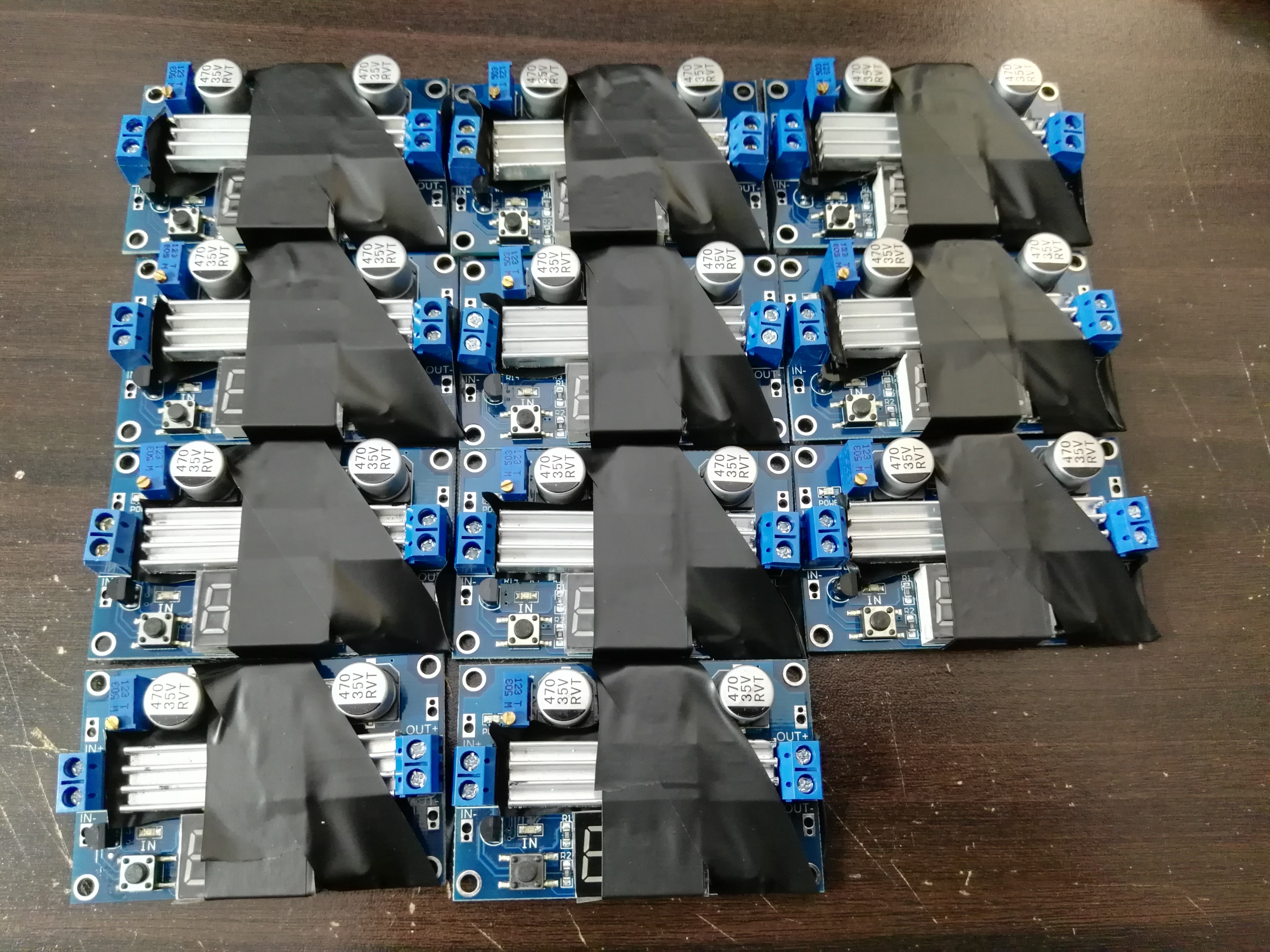
I ordered 12 of the following:
"DC-DC 100W 3-35V to 3.5-35V Boost Step-up Modules Power Supply LED Voltmeter New"
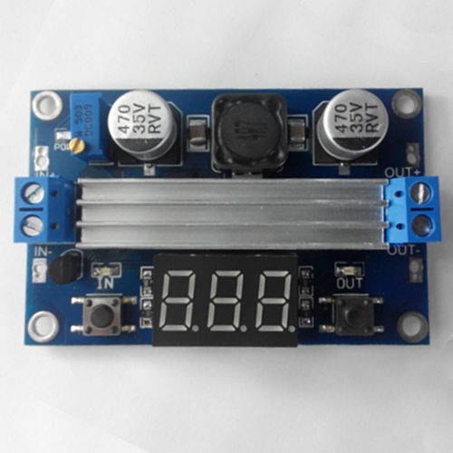
Unfortunately, the heat sink that goes over both the output diode and the main switching transistor does not sit level (the semiconductor packages are at different heights). This meant that I needed to have separate heatsinks for each semiconductor! Fortunately, the heatsinks came unconnected with a tear away adhesive backing. All I needed to do was hacksaw each heatsink in half, peel off the backing and attach it to where it needed to go to fix the problem. The tape is for insurance.
Boost converter Testing
To test the 11 boost converters (may that 12th one rest in peace), I used a battery charger to apply a controllable load to one of the modules. The beautiful thing about the iCharger is that if the input source (the boost output) starts to decrease (voltage), it backs off the battery charging current. This effectively automatically tells me the current limit of the boost converter. As I wanted to boost a 0-16V super capacitor (4266J) to 24V @ 20A, I needed to know if 10 of these boost converters could fill these requirements. The worrying part is the necessary overrating due to the very high gain requirements as the capacitor voltage approaches zero. Below was what I measured for a single boost module:
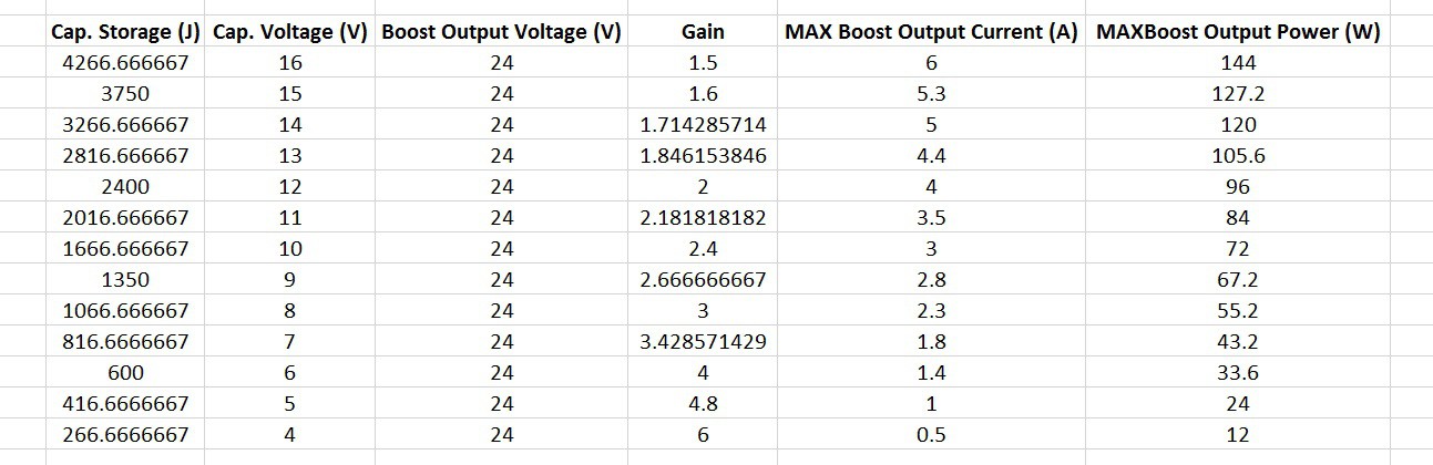
We can see the massive power drop off as the voltage gain increases to accommodate the dropping capacitor voltage. Now there are two concerns:
- The capacitor current shouldn't exceed 60A for too long (capacitor is rated to 120A "peak" - whatever that could mean).
- How much energy can be extracted from the capacitor before the 24V/20A/480W output rating can no longer be maintained?
Lucky for us, Excel makes this easy to visualise:
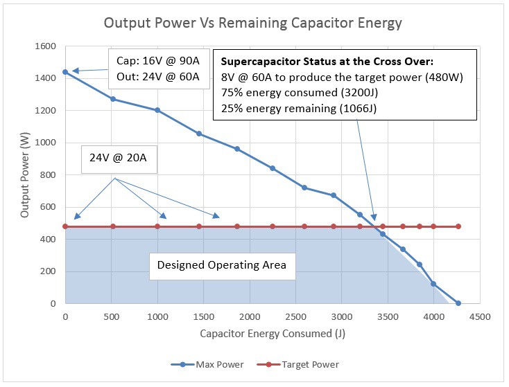
By looking at the capacitor state of charge through the remaining energy, we can see how the system will act over one discharge cycle. Seen in blue is the maximum possible power that can be drawn from the output at 24V. Seen in red is the rated power at the output that is ideally maintained regardless of the energy consumed from the capacitor. The overrating of the charged state capacitor is a bit extreme, but very much worth it for the extended operating area. Within the designed operating area (blue-filled region), the input current never exceed 60A, even if the 24V/480W output is maintained (though the input current will vary from 30A to 60A).
However, something magical happens at the 75% (3300J) discharged point. Although the power drops below the rated 24V/480W due to boost converter limitations, even if it didn't, the capacitor current would have exceeded the 60A limit anyway. Effectively, these two limits have aligned by chance, not only maximising the capacitor energy that can be used (at 24V/480W), but automatically limiting the capacitor current within safe limits. The only protection for the entire system required is a slow blow 20A fuse at the output!
Discussions
Become a Hackaday.io Member
Create an account to leave a comment. Already have an account? Log In.