Michael R Colton
-
Transmit, Audio, Graphics, Oh my!
10/13/2014 at 07:30 • 0 commentsSorry for the absence of posts! Time flies, but I am still working hard!
I've made some rather nice improvements to the audio code. I've greatly sped up the graphics drawing code, which means everything runs faster and the radio feels more usable in general. And I've added the ability to transmit (very weakly, but still)
The capacitive touch sensors work, and the GPS code is coming along.
Still lots to do!
I forgot to mention it in the video, but I took the PSDR to the swapmeet, set up a table, and showed if off. It seemed to be well received (get it?). Met some very nice folks and scored an amazing deal on that Kenwood radio (it was a gamble though, I honestly wasn't expecting it to even turn on without work).
It's my understanding that the final 5 will be announced today! Wish me luck!
-
Semifinals Video
09/29/2014 at 06:46 • 1 commentThe audio was missing from part of the original Semifinal video, so here's the fixed one:
Here's the video of the Semifinal judging. It shows off the PSDR2 a little bit. Enjoy! There will be more info on that soon, now that I have met the judging requirements. Wish me luck!
P.S. Judges, I'm honored that you'll be taking some time to look at my humble project. I hope you like it!
Just in case it matters, here is the original video:
-
Getting (en)closure
09/22/2014 at 06:35 • 0 comments![]()
![]()
Greetings! The wait for PCBs it killing me. They should get here this week (unless I am really unlucky) so I might have a day or two to assemble it, write enough code to do a demo, record it, edit it, and post it. And I thought my boss pushed me hard!
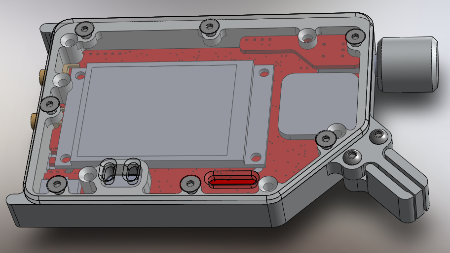
Anyway, I'll do what I can. In the mean time, I decided to work on the enclosure. I'm going for rugged, usable, and maybe a little cool looking, while keeping it manufacturable. What do you think? It is not done yet, but it's pretty close.
It's going to be a little thicker than I had hoped (but still less than 1") due to the encoder and LCD being too tall. I want to see if I can shave those down next time. I'd like to get it closer to 0.5" thick. The whole thing will be roughly the size of a deck of 3x5 flashcards.
I designed the PSDR2 to support three options for Morse code paddles, touch sensitive, normal (contact closure style), and external. What you see here is the normal style, because it's the hardest to build.
The big square to the right of the LCD is the GPS antenna. The longish hole along the bottom edge is for programming and debugging (the board will also be programmable via USB for people that aren't planning on doing any development). The other two holes along the bottom are for the speaker.
I have some ideas for some documentation I want to do as well. More on that later.
-
PSDR2PCB
09/15/2014 at 05:31 • 4 comments![]()
![]()
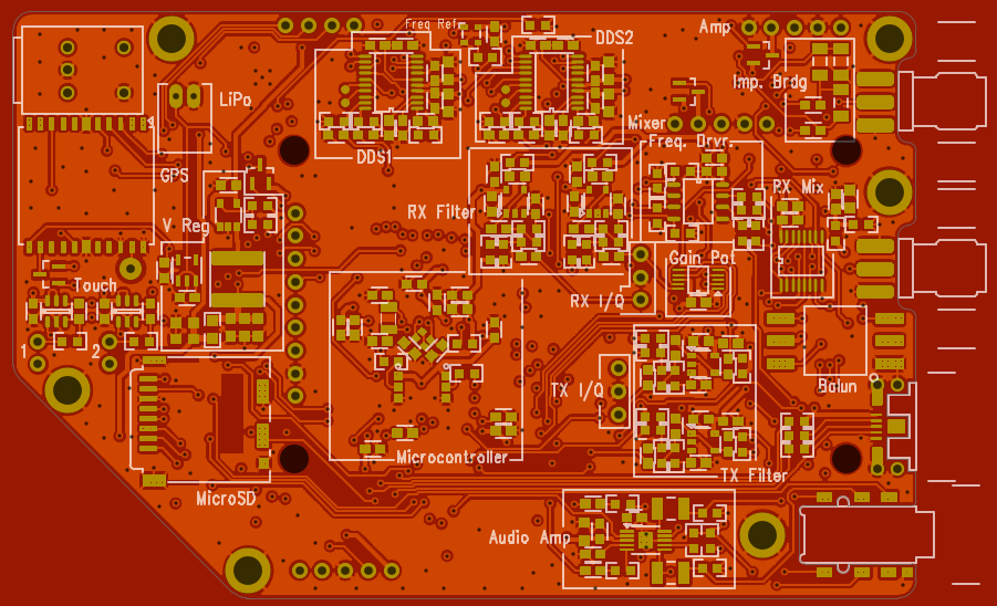
Hi loyal minions! After quite the marathon of board layout, the PSDR2 PCBs are complete. I am trying dirtypcbs.com . They've got great prices for 4 layer boards and have reasonably priced rush/fast shipping options. Though I was sad to learn that I can't get a red board with gold plating AND rush the order... Red was going to look really good, but it doesn't look like that's going to happen for the first batch of PSDR2s.
Anyway! I'm glad I pushed so hard to get these out. I might just have something cool to show off by the end of the month.
I'm pretty happy with the layout, but I didn't have time to give it some of the polish that I usually like to. Routing for the power traces isn't ideal, and I didn't bother with proper impedance considerations..... I think it will be okay.
So I generally try to do something new on each PCB I produce, if I can. This time it's a bunch of new components, a new fab house, and you'll notice that I left off pretty much all of the reference designators so I'd have room to label the circuit blocks. I think it's pretty neat, but it's going to mean that I'll have to prepare well illustrated assembly diagrams. What do you guys think? How important are reference designators really?
Speaking of assembly, there are a few parts that will pretty much have to be installed with a hot air pencil or a reflow oven, I really tried to make it possible to assembly without those, but some of the parts aren't available in any other package.
-
PSDR2 Teaser
09/13/2014 at 04:34 • 0 comments![]()
Hi everyone, has it really been ten days since my last update? Sorry about that. As I said in my last update, I have been working very hard on getting the PSDR2 designed. I've been spending every spare moment on it and took the last day and a half off from work to get this thing out. It needs to get sent off for production as soon as possible or I wont get it back in time to show it off for the next round of judging!
Anyway, I'll have it done by this weekend, hopefully have it back a week later-ish. I don't think I'll have time to write much code to take advantage of the new features though. A month is not a long time.
This has been one of the most challenging boards I've ever designed, and the most thought out, which helped. I'm pretty happy with how it's going. With the exception of the final power amplifier and 2-Meter mixer, it's got everything I wanted to put in. It's PACKED! I'm so excited!!
Oh yeah, this version will have an enclosure too. :D
Wish me luck! Back to work!
-
Final 50
09/03/2014 at 06:43 • 1 comment![]()
Hi guys! Sorry it's been so long since I've updated. Believe me, I haven't forgotten. I've been hard at work! As you may know, the PortableSDR was selected as one of the 50 semi-finalists for the Hackaday Prize! Thanks everybody! Wish me luck!
The next round of judging is less than a month away so I am trying really hard to knock out the next revision of the PSDR. So far I've got dual capacitive touch keys (for morse code), battery charge controller, GPS, and the VNA/Antenna analyzer blocks. Even bigger microcontroller. Real time clock support, digital gain control. MicroSD slot.
Anti-aliasing filters are going in all over the place, built in speaker, mic, and an earphone connector that works with smartphone-style earphones/microphones will be included.
There are a few things that wont make it into this version (RF Amp, 144Mhz mixer) but for some things I am including a "shield" style place to plug in modules. I don't think I am going to get a new LCD in there this time. Also, PJRC's amazing work at speeding up the driver for the ILI9341 makes me think I may not need to switch to the parallel interface on the LCD (which takes A LOT OF PINS!)
I hope to have the schematic changes done in a few days and a PCB design as soon as possible after that (a week?). I'll keep you guys updated!
-
S-Meters & Reasons To Buy Tools
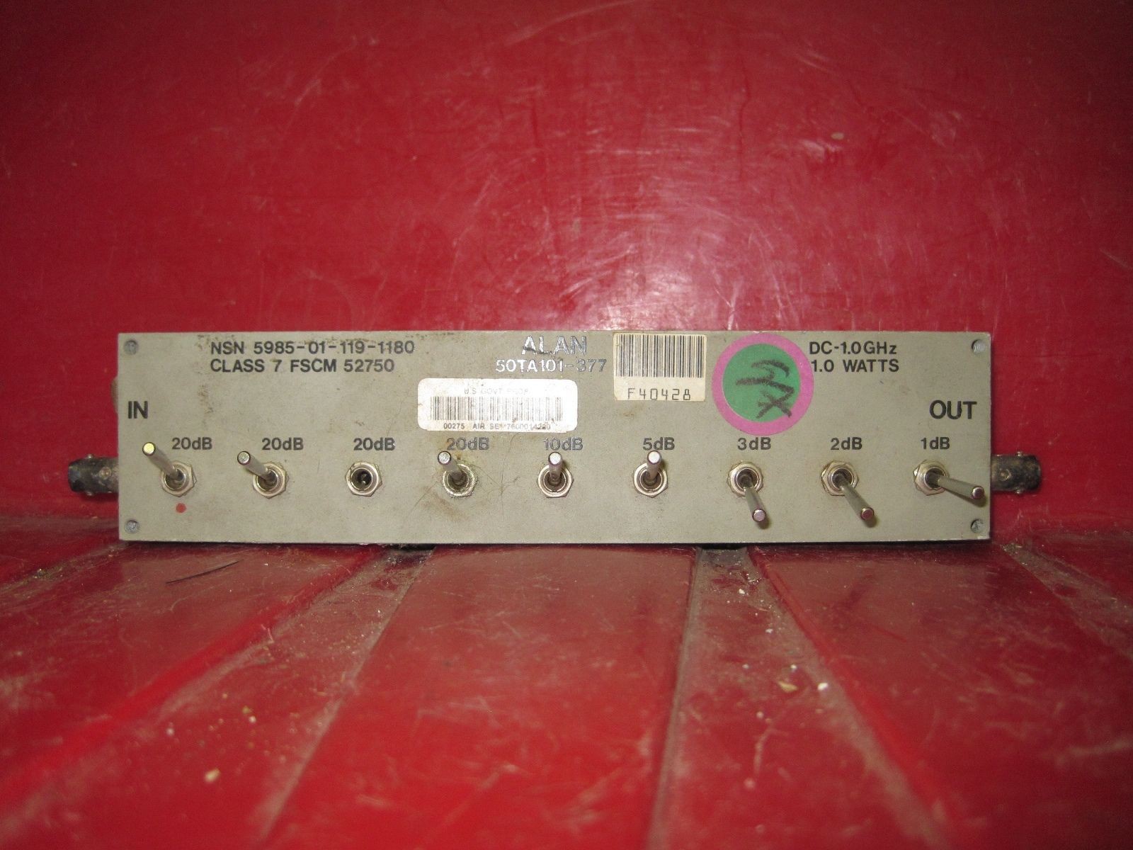
08/22/2014 at 05:11 • 5 commentsJust how gross was the attenuator?
![]()
It's fun having a project that gives me an excuse to buy new tools. Still, I would imagine for most people, an attenuator is about the most boring tool in existance....
-
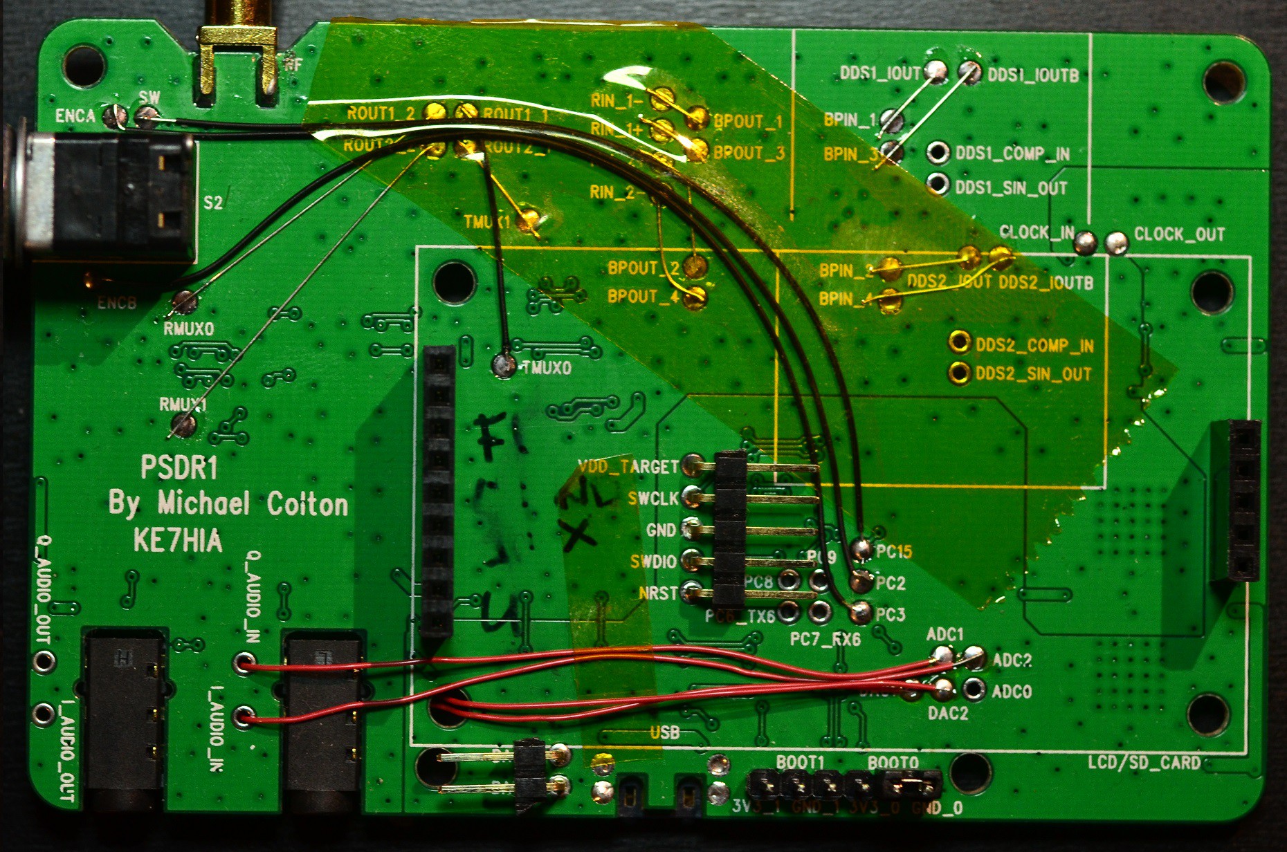
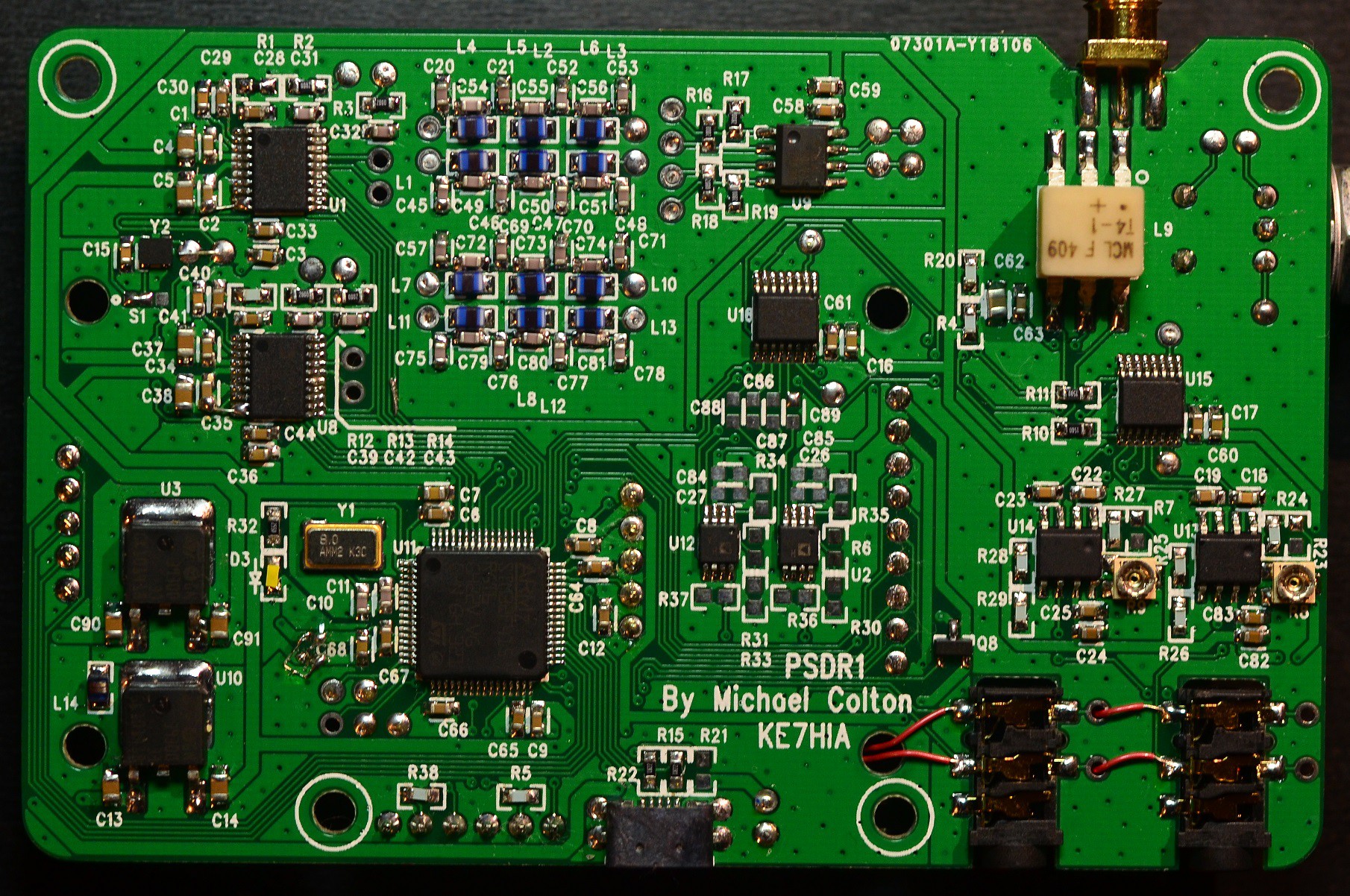
PDSR1 Closeups
08/17/2014 at 23:14 • 2 commentsI still have intentions to make an assembly video. But for now, I hope this will be of some use. Nricciar and John Laur are basically done assembling their PSDR1s, but both have asked for better pictures of the board so they know where to wire the connections between blocks.
Both have given good feedback on things that can be improved and little mistakes I made along the way. In my defense, the 75 MHz oscillator isn't too hard to solder with a microscope, hot air pencil, nerves of steel, and the hands of a surgeon, just saying. Also plenty of sleep the night before.
Go checkout Nricciar's Imgur account again (in the previous post) to see how far he's gotten. Awesome! It's pretty surreal to see those boards going together!
Does Hackaday.io allow posting images in the comments? If so I'd LOVE to see what other people are putting together as well.
![]()
![]()
-
PCBs to the People!
08/12/2014 at 05:24 • 1 comment![]()
Hi Everyone! People are starting to report that they have received their PSDR1 boards! Nricciar has been keeping me updated with his progress. And he's doing a great job of documenting it along the way. That's his picture above. Check it out! (I hope you don't mind my linking this!)
That picture includes a VERY IMPORTANT FIX! See under "C10" there are two traces that need to be swapped or you will blow the STM32F4! (Unfortunately he found that out himself before I could warn him. Hopefully that hasn't happened to anyone else yet!) I've been meaning to make a video that shows how the PSDR1s need to be built up, but I haven't been able to get to it yet. Sooo busy.
I will make a video for that soon, but I still haven't made my official project video for the HackADayPrize and the deadline is only a few days away, so I'll probably do that first. Those that are building, the above fix is the only one that must be done to avoid damage.... I probably need to make a FAQ too... Hmmm.
-
Morse Code Contest
08/03/2014 at 06:13 • 0 commentsHowdi, here's a ghetto video update of where things are. There was a ton of activity on the Morse Code segment of 40 Meters (about 7MHz) tonight, so I thought I'd recorded. Also, the STM32F429 Discovery Development Board arrived, it's display performance is amazing! (It works out to over 800 frames per second! Not that the LCD could actually update that fast.) Finally, I have volume control working, it's not logarithmic yet (like our hearing) so the volume is control is really sensitive when it's quite, and not sensitive at all when it's loud.
I've been busy with work and a freelance project, so I haven't made as much progress as I'd like. But I am still plugging away at it!
PortableSDR
Fully stand-alone HF (Shortwave) Software Defined Transceiver & Vector Network Analyzer. Designed for rugged portable use. Highly hackable.