 Jon
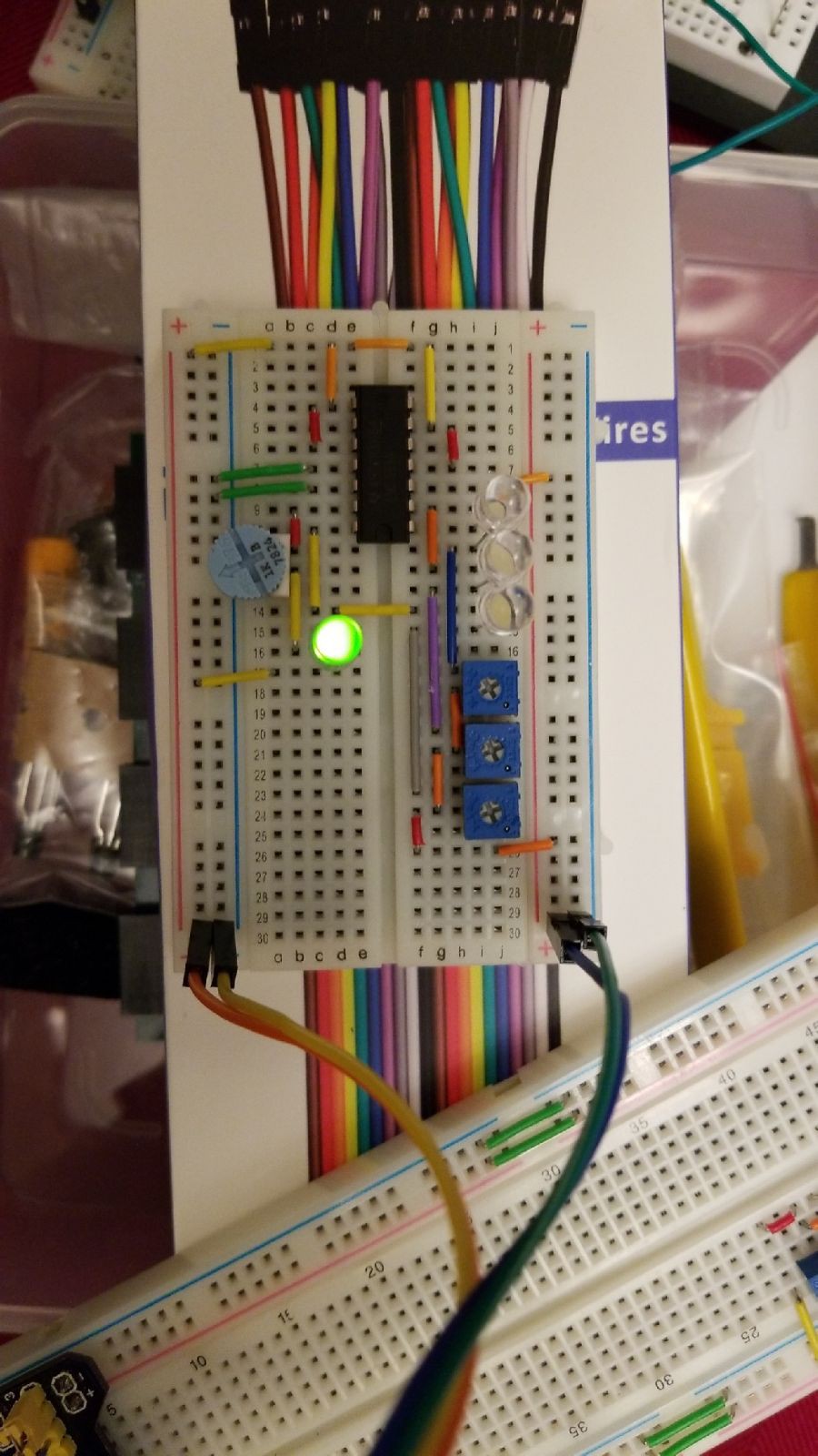
JonA comparator circuit was mocked up to bridge the voltages on the Vista 20p security panel associated with each switch zone. Each comparator was assigned three (3) of the total six (6) switch zone inputs. The outputs of the comparators were each wired to an LED and comparator to provide both a reference voltage value and visual status indicator. The fourth open comparator input on each chip was wired to power an always ON LED.
The comparator circuit was required because the selected security panel voltages could range from as low as zero (0) volts to twelve volts. Switches were configured using the security system standard of normally open with End of Line (EOL) resistor. In normally open status the circuit voltage would be five (5) volts DC through the specified EOL resistor (2k ohms). A short circuit / closed switch would drive a zero (0) volts level. Open circuit voltage was 12 volts, which would only be present under fault conditions such as cut wires.
However, as any range outside of 5V could damage the selected EEPROM inputs the comparator was used to compare the voltage reading at the high side on the security panel to a reference voltage (3.3V was selected as an arbitrary value sufficiently between zero and 5).
Discussions
Become a Hackaday.io Member
Create an account to leave a comment. Already have an account? Log In.