 David Shelenev
As mentioned above, the RM1 takes design features from commercial robotic arms, and realizes them in a more affordable way. Here's a quick rundown on how these features are addressed:
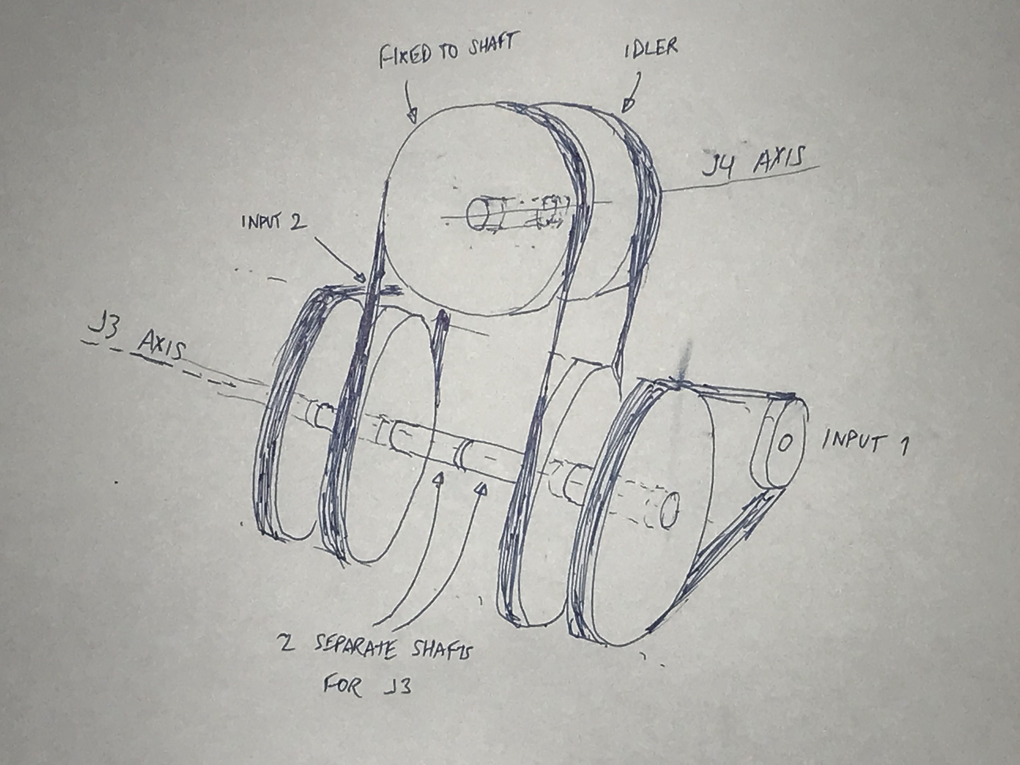
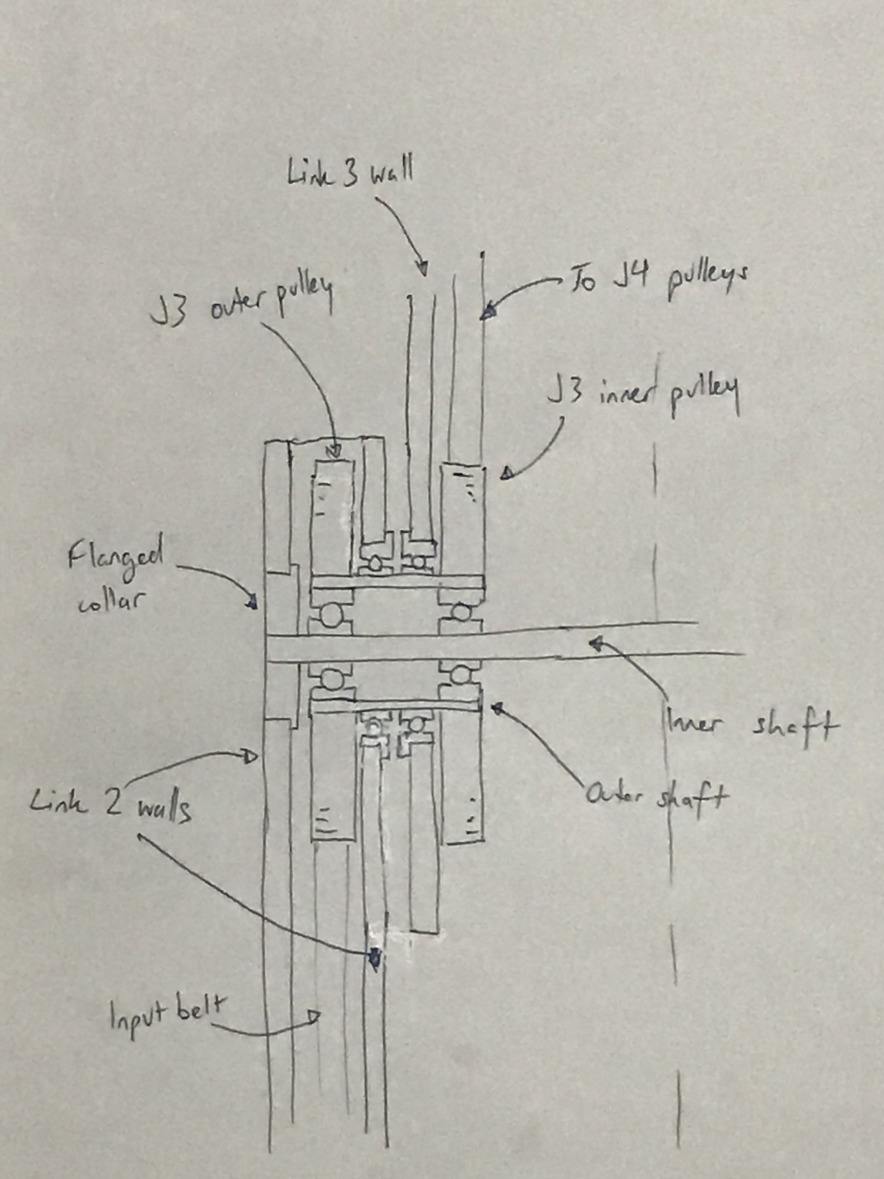
- Low backlash gearboxes: If you know about robotic arms, you know that backlash is the precision killer. Commercial robot arms use (expensive) zero backlash harmonic gearboxes. Although there is no direct low cost replacement for these gearboxes, we can use a series of belts and pulleys as a gearbox to achieve relatively low backlash at very low cost.
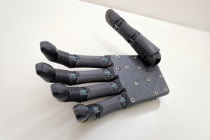
- High frame rigidity: Rigidity is not only important for the arm's positional accuracy, it also prevents the arm from flexing under high acceleration and load. Almost all commercial robot arms use cast steel or alloy frames, providing very high rigidity. We can achieve high rigidity affordably by using a design made from interlocking carbon fiber sheets.
- Brushless servo motors: Commercial robot arms use expensive brushless AC servo motors, with optical encoders or resolvers for position feedback. We can achieve similar results with an affordable brushless DC hobby motor, a low-cost capacitive encoder, and the open source ODrive driver board (by ODrive Robotics), which makes our cheap hobby motor perform almost like an expensive industrial servo motor. Unlike stepper motors, brushless servo motors are capable of high torque and positional accuracy, quiet operation, and have a lesser tendency to overheat under high load.
- Closed-loop control: Since industrial robot arms move at high speed and with high torque, positional feedback is important to prevent the arm from crashing. Instead of using stepper motors with no position feedback, which are prone to skipping steps and losing track of their position, we use encoders to "close the loop", so the arm can move accurately and repeatably.
- Sound mechanical design: The final piece of the puzzle is a good mechanical design, which is strong and light, but still easy to assemble and service. Luckily, the broad strokes design is already complete, so now it's only a matter of filling in the details in CAD.


 Supercell
 Naman Pushp
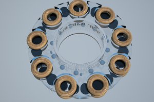
 Kostas Lagogiannis
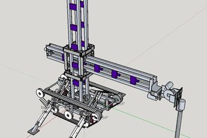
Is it possible to collaborate on the 3D CAD assembly by branching the project or are you (the creator) the only person that can make any changes? I see the GIThub link, but not one for CAD.