Close
0%
0%

Hardware Reverse Engineering Learning Platform

a hardware version of your crackme and reverseme games for learning hardware reverse engineering techniques without expensive tools

Similar projects worth following
I enjoy trying to reverse engineer the famous crackme and reverseme executables in my spare time. After reading the xbox reverse engineering book by bunnie I went looking at the my options for learning and experimenting with hardware reverse engineering. Unfortunately the options are few and expensive.

This is my attempt at creating an opensource inexpensive learning platform that can be used to learn various RE techniques without spending too much money on expensive tools. By slowing things down you can use cheap tools such as the buspirate and logicpirate

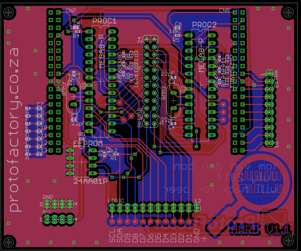
The hardware reverse engineering platform is basically a shield for the new stm32 nucleo boards using the st-morpho connectors. It contains two arduino compatible microcontrollers and an eeprom. There are 9 data lines connected between the two microcontrollers and there is also i2c lines connecting the mcu's with an eeprom. The nucleo board handles loading the reverse engineering scenario on the shield (firmware on the avr's and data on the eeprom). 

Design Overview

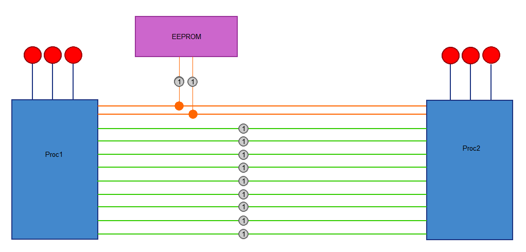
This allows anyone to easily create firmware that depicts a possible RE situation. For example the two mcu's can communicate with each other using a certain protocol.

Test pins are added on all the data lines for connection to RE tools. There are also jumpers for breaking connecting between the two mcu's or to connect your own tools for inserting data to 'crack' the scenario. 

Arduino was chosen for the target mcu's because anyone needs to be able to create new RE scenario's without having to spend too much time getting the hardware to work. It's all about the reverse engineering and not firmware development.

The nucleo shield handles the setup of each RE scenario, basically on the pc side it will accept the firmware files and setup the avr mcu's with the new code for reverse engineering.

So it's re-usable for different scenario's and slow enough to use cheap tools :)

For updates you can also join the mailinglist.

  • 2 × atmega328 Microprocessors, Microcontrollers, DSPs / ARM, RISC-Based Microcontrollers
  • 1 × AT24C256 Memory ICs / EEPROMs
  • 1 × NUCLEO-F401RE STM32 Nucleo development board for STM32 F4 series
  • 2 × 16 Mhz Crystal Crystal
  • 13 × Red Led 0603 LED

View all 12 components

  • Hack-A-Day Prize Entry Ready

    Tom Van den Bon08/20/2014 at 12:59 0 comments

    So I woke up this morning without any idea of the what I'm going to do for a video (ok, lots of ideas but nothing practical). I had a little bit of time during my lunch break so decided to give it a quick go and create something using VideoScribe. It's not the prettiest video out there, but it fulfills the entry requirements of a 2 min video.

    Entry Requirements: (for 20 Aug)

    (1) System Design Pic ... Check

    (2) 4+ Project Logs ... Check

    (3) 2 min video ... Check

    (4) Explain how your project is connected? .... uhm

    Well, I was hoping it was kinda obvious but a closer look at everything I've written and I'm not sure if the reader would understand how it's connected. In simple words, the main concept of this project is to be able to reverse engineer communication between two connected microcontrollers... aah see what I did there ? ;)

    I'm not sure if my project is really worthy of winning a prize such as going to space, but it's something that I've wanted to do for a long time (this project, not go to space ... ok, going to space as well but that's not what I meant... right?) and the contest has been motivation to get this project off the ground.

    Let's hope I didn't miss a requirement somewhere ?

  • v1.1 is alive!

    Tom Van den Bon08/08/2014 at 13:53 0 comments

    I soldered up the new board, hooked it up onto the nucleo and loaded some test programs and all seems good. Communication to the two RE processors work and all led's go blinky. Time to write some real code now. Both the RE processors (the two atmega328's) are loaded with the arduino bootloader. Next step is to write code for the nucleo board that can upgrade both RE processors using the bootloader to setup the RE scenario.

  • New PCB V1.1

    Tom Van den Bon08/06/2014 at 15:54 0 comments

    Haven't had time to do a lot of updates, but received the new pcb's today and I'm very happy with how they turned out. I'm not always happy with the quality of the silkscreen so I tried to do some stuff with the copper layer. Looks great :)

  • HWRE V1.1

    Tom Van den Bon07/22/2014 at 16:58 0 comments

    So haven't managed to keep my logs updated as much as I would like to. With regards to the previous pcb, they are up and running although they do have a few small mistakes and also a few things I didn't like, so I spent a few hours updating the pcb. (I'll take some photos of the assembled board with a more detailed post on what exactly is wrong and what I added to the new boards)

    I present to you HWRE V1.1

    As you can see I'm also using this as a test for some graphical stuff. Not sure yet if the fabhouse will accept it, but we'll see ;) Still need to do some checks, but will be sending these boards away for fabrication in a few days :)

    On the software side, I'm making good progress. Will be posting what/where and how in the next couple of days :)

  • V1.0 Boards arrived!

    Tom Van den Bon07/04/2014 at 15:15 0 comments

    So the first batch boards arrived :) Wasn't expecting them before next week, but looks like they cleared customs very quickly! Will build them up this weekend and start testing everything.

  • Overview of the HW Hackme Hardware

    Tom Van den Bon07/03/2014 at 08:52 0 comments

    The HackMe Shield

    So here is a basic overview of the HW HackMe shield. The main parts consist of two processors/microcontrollers connected by 9 datalines. Each processor is also connected with i2c lines. Hooked onto the i2c line we have a eeprom. Each processor also has 3 indicator led's. 

    Each of the grey dots (1) are testpoints where you can hook up your analyzing and testing equipment. Not shown on the diagram but each line can also be disconnected by removing jumpers.

    So, in it's simplest form we can now load a hackme scenario on the two processors (with data on the eeprom) and using the various test points reverse engineer the hardware.

    For example, lets say the two processors are communicating with each other using an unknown protocol. We can now hookup a logic analyzer to the test points and try to figure it out (reverse engineering).

    After reverse engineering the process we can now either move on to another scenario (using the same board) or maybe even take this scenario further by manipulating the data communication. By removing the jumpers between the processors we now have points to hookup our own tools and send false data to the real processor....

    The eeprom adds another dimension because data can be stored on there which the processors need to communicate with each other. Using the test points on the i2c lines we can easily sniff the activity, dump the data for analyzing or even write our own data onto the eeprom.

    Learned everything you need to know about this technique? Then just load another scenario to reverse engineer or to practice with.

    So what about the nucleo board?

    The diagram above is essentially the whole 'reverse me' hardware, but for each scenario you need to load onto there you would need to reprogram each of the microcontrollers and load data on the eeprom. It works, but is time consuming. We're here to learn new stuff not reflash the board over and over. This is where the nucleo board comes in. It has a single serial connection to your pc. It takes care of receiving all the scenario data from the pc app and setup the scenario on each microcontroller and load data on the eeprom chip. By making it a 1 time operation you can spend more time on the reverseme scenario :)

    The reason for choosing the nucleo board is mostly because it's so cheap. It's available for between ~$10 depending on where you buy it. Incorporating all the parts onto the main shield would make it more expensive (especially on low qty).

    Until next time :)

  • Boards Shipped and More Info

    Tom Van den Bon07/02/2014 at 09:39 0 comments

    So the boards are shipped and on their way. Very excited to give them a try. Software is also making good progress. Documentation on the other hand is something I still need to work on :p I've received a lot of queries about buying these. Depending on the interest I might look into that. If you want to be notified should these boards become available then feel free to join this mailinglist for updates. Will be posting photos and more regular logs as soon as the boards arrive :)

  • Current Status - 2014/06/20

    Tom Van den Bon06/20/2014 at 08:53 0 comments

    I have designed the first version of the boards and they are at the fabhouse for manufacturing. Files in the github is therefore untested! Currently working on the source code while waiting for the pcb's

View all 8 project logs

Enjoy this project?

Share

Discussions

flaviu.ionutz wrote 04/28/2015 at 08:52 point

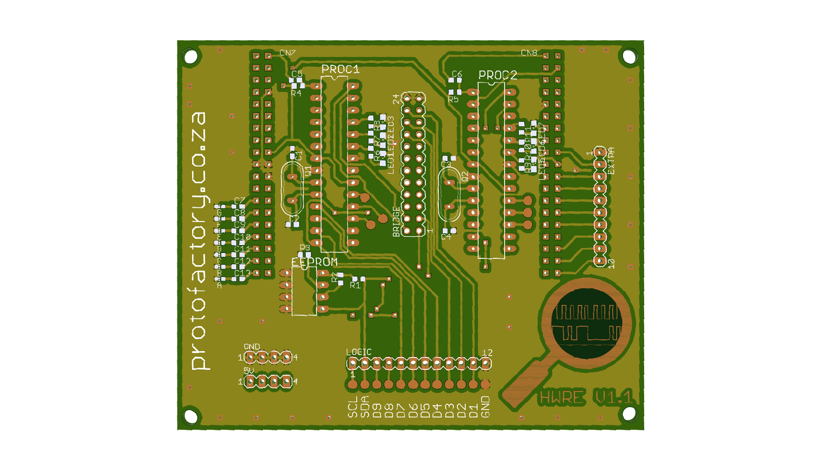
If I look in the Eagle PCB design you posted I can see one OVERLAP!

  Are you sure? yes | no

Tom Van den Bon wrote 06/27/2014 at 11:07 point
Hi Adam,

Well, I'm trying to make it as userfriendly and inexpensive as possible so I don't see any reason why it can't be used for both?

T

  Are you sure? yes | no

Adam Fabio wrote 06/29/2014 at 03:08 point
Sounds good to me! We need more learning tools like this.

  Are you sure? yes | no

Adam Fabio wrote 06/26/2014 at 06:00 point
Hardware hacking for the masses! Thanks for entering The Hackaday Prize, Tom! Do you think this board will be more of a tool for hackers at home, or a classroom device?

  Are you sure? yes | no

Similar Projects

Does this project spark your interest?

Become a member to follow this project and never miss any updates