 Just4Fun
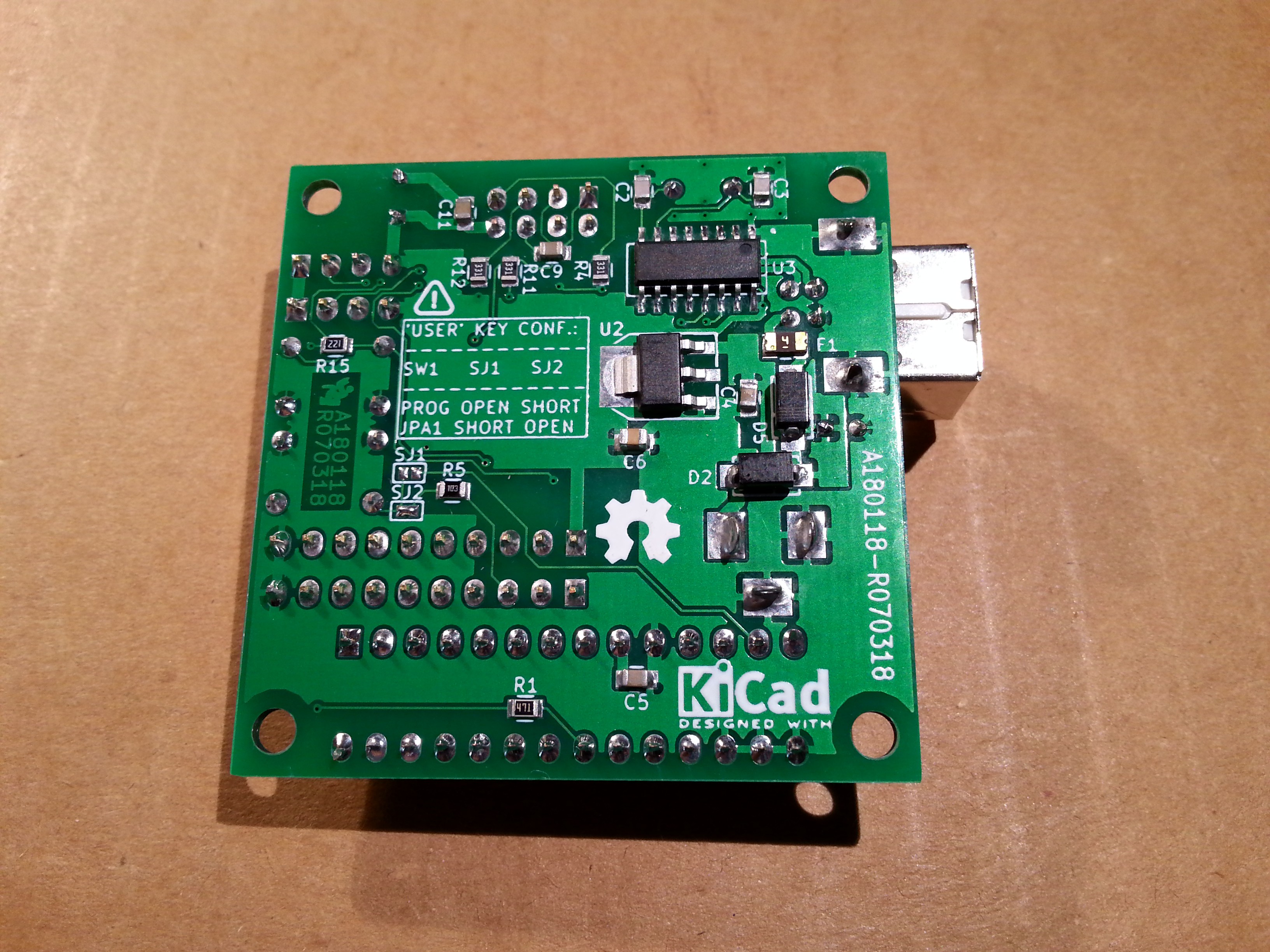
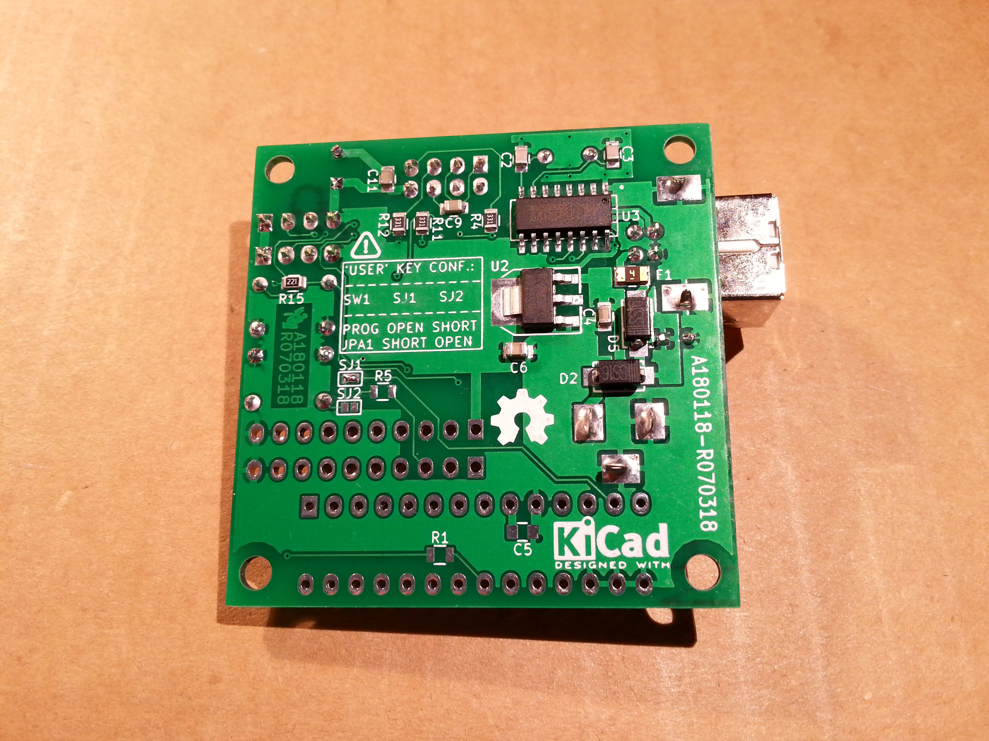
In the following images it is possible to see the front and the back of a completely assembled board, including the optional 16x GPIO expander (MCP23017 powered at 3.3V):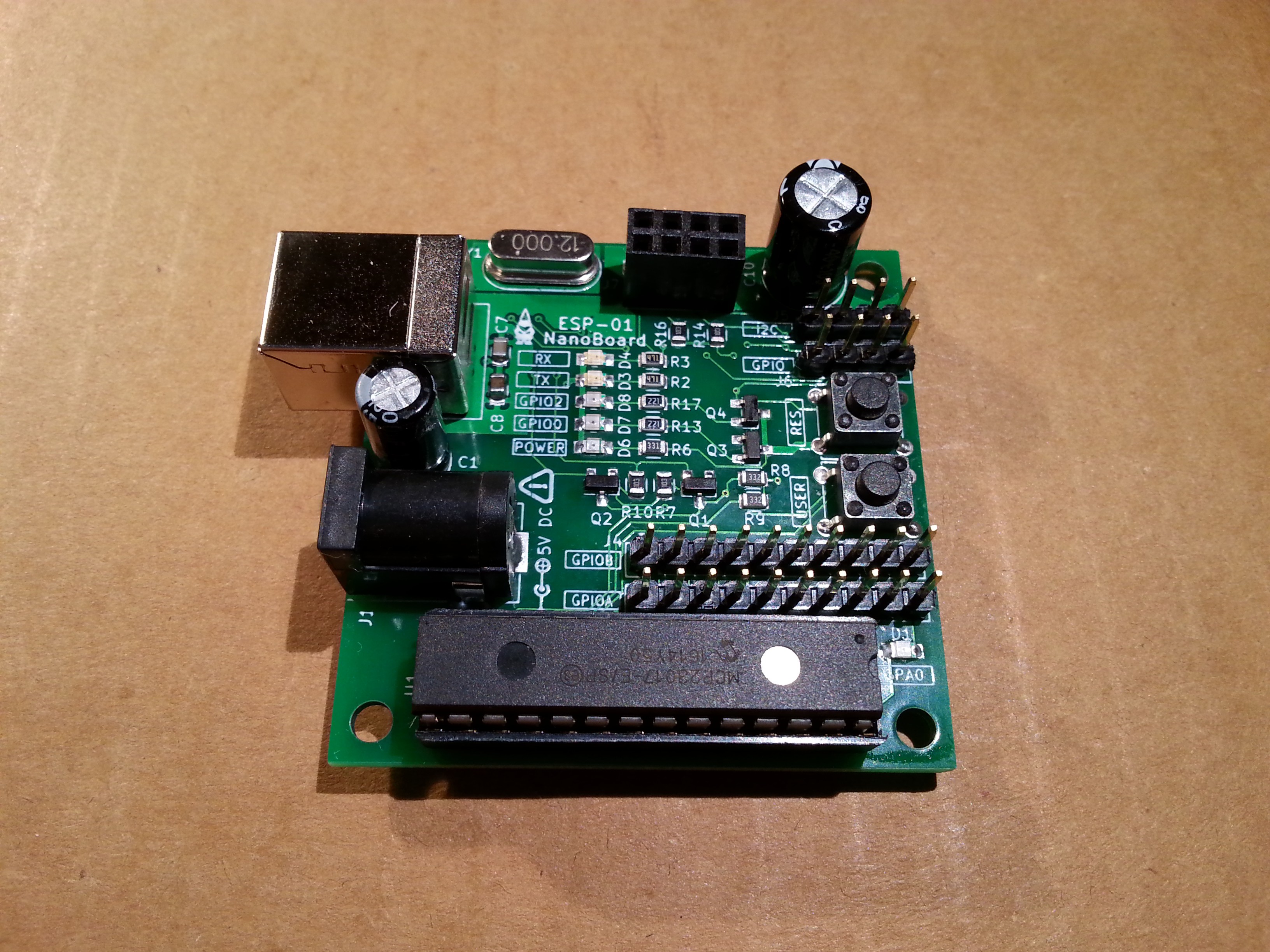
 The service used to make the PCBs was JLPCB. They kindly offered to me to test their service, so I did:
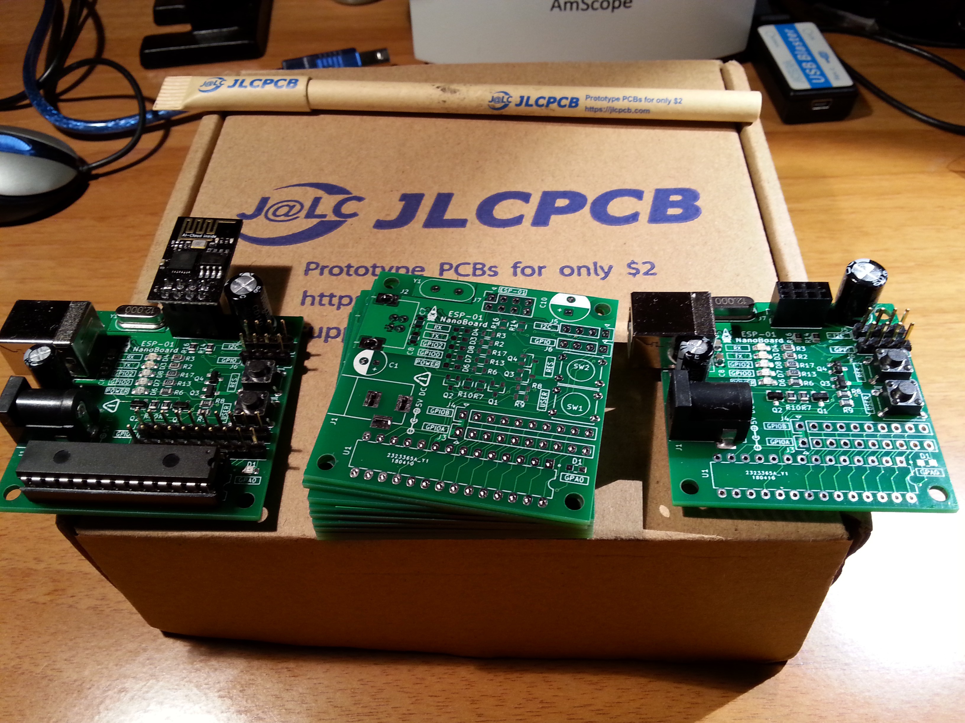
and the result was good for my needs!
Next video shows the NanoBoard in action, loading a blink demo program using the Arduino IDE (Windows 10 host). The upload process do not require to press any key (like for the well known NodeMCU):
Please note that you need before to set "nodemcu" (instead of the default "ck" ) as "Reset Method" inside the "Tools" menu of Arduino IDE.
The optional expander
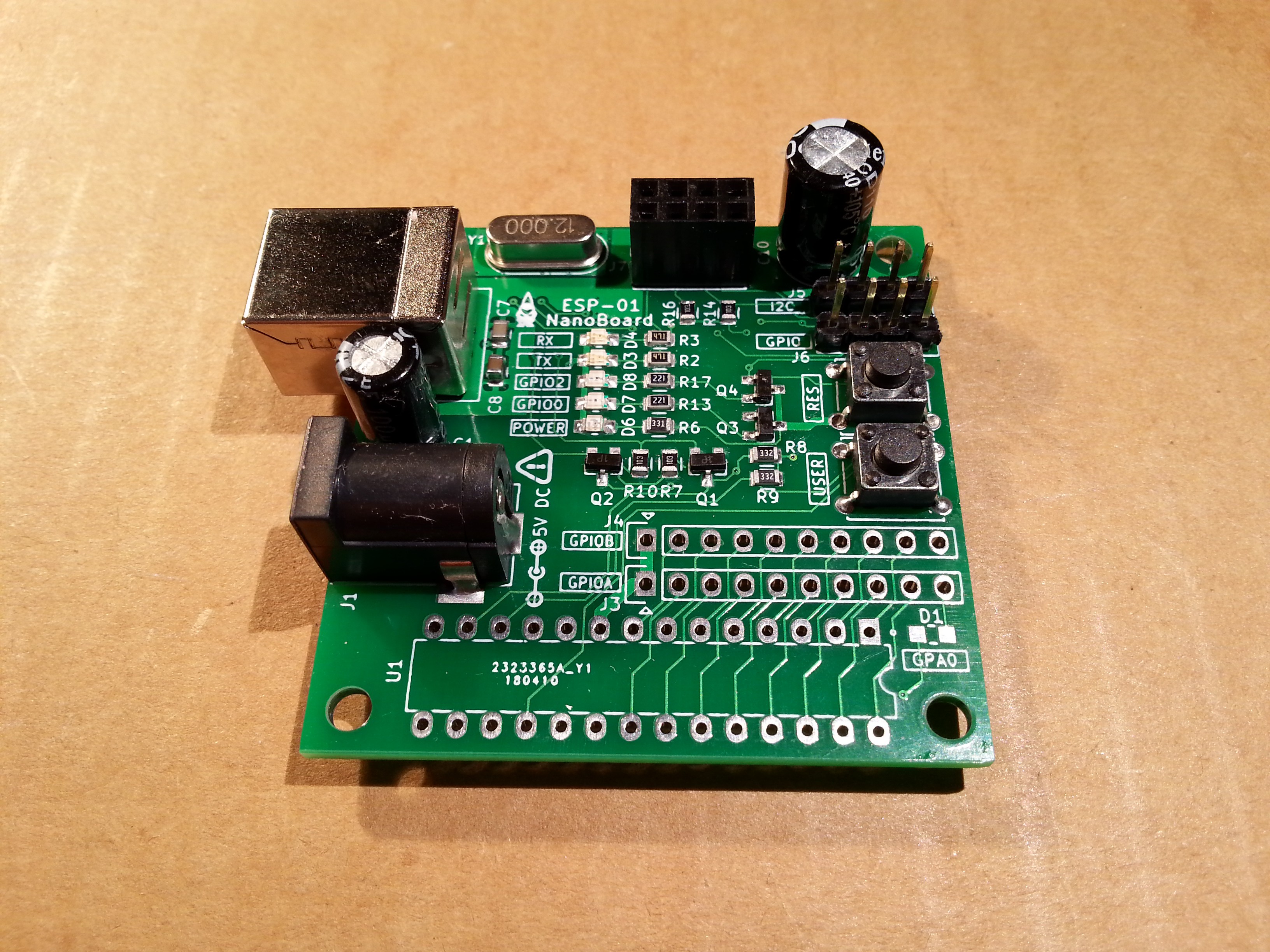
The ESP-01 NanoBoard has an optional 16x GPIO expander (see the schematic). If you decide not to want it, just not to populate the components inside the dotted optional part of the schematic.
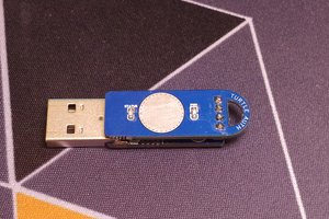
Here it is a NanoBoard "lite", without the optional expander:
 Samuel
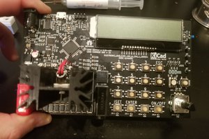
 schwarzrmsu
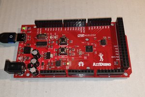
 icstation