 Sugapes
In the last few days I finished the basic skeleton of my 3D printer, and now it almost looks like one!
The darn thing came out bigger than I imagined though! I was aiming for a build volume of around 30x30x30 cm, and I gave enough margin to achieve it, so in the end my "desktop" printer no longer fits on my desktop! Well my desktop is kind of small anyway...
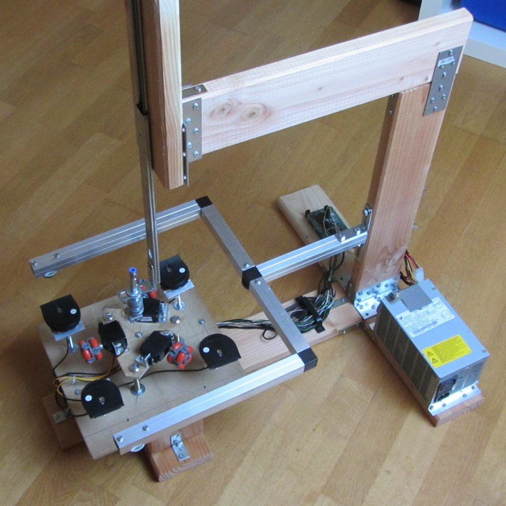
However in this first iteration I might not even reach those marks. First of all the aluminium support you can see above the XY drive system is limiting the Y axis travel to around 20 cm or so, and the drawer slider I am using for the Z axis is actually limited to 27 cm when fully extended. Those are the maximum values, but the main limitation is still the XY surface that I am yet to find the best candidate for. Due to the way things are setup the full XY surface would need to be around 60x50cm, (for a 30x20cm build surface), it also needs to be pretty flat and not to heavy, and additionally allow the omni wheels to grip well. To make a long story short, It has been tough to find a material that fits all those three constraints (and yet while not being too expensive). I was aiming for some sort of melamine tray, but they don't seem come in those big dimensions, so the search continues.
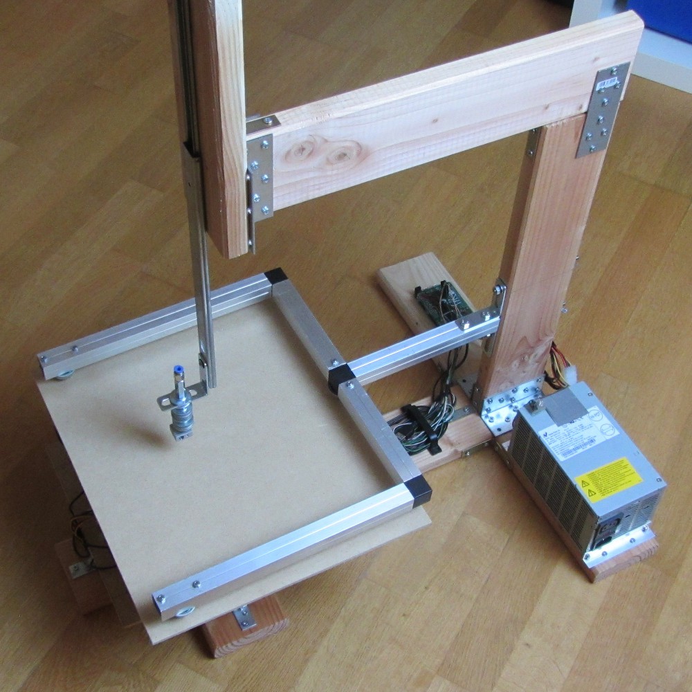
This is how it would look with a (too short of) XY surface. Unfortunately the MDF leftovers I had lying around aren't big enough to give it just a trial run.
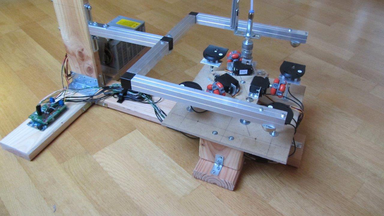
The next picture gives a closer look of the XY drive system. The main idea is for the wheels to push the XY surface against a rigid structure. This has two main purposes. One is since the XY plane is much bigger that the distance between the wheels the aluminium structure above prevents it from tipping over. The other reason is to prevent Z axis oscillations due to the unevenness of the omni wheels. To that effect the holonomic drive system is mounted on a suspension that pushes the XY plane against the big aluminium square above it (it has 3 caster balls that can barely be seen in the picture bellow).
The shape of the XY support structure is not the ideal one to allow the full extent of the Y axis, but it was the easiest to build. I'll stick with it for the time being for my initial testing, and replace it later on with something more sturdy and which does not limit the Y axis travel (to let it have the full 30 cm range instead of the current 20cm).
Unfortunately I will not be able to work on the hardware part of this project for the next few weeks as I will be traveling on vacation with my family. I'll try work (in the evenings) on the code, and on the documentation, so it won't be a complete halt.
Discussions
Become a Hackaday.io Member
Create an account to leave a comment. Already have an account? Log In.