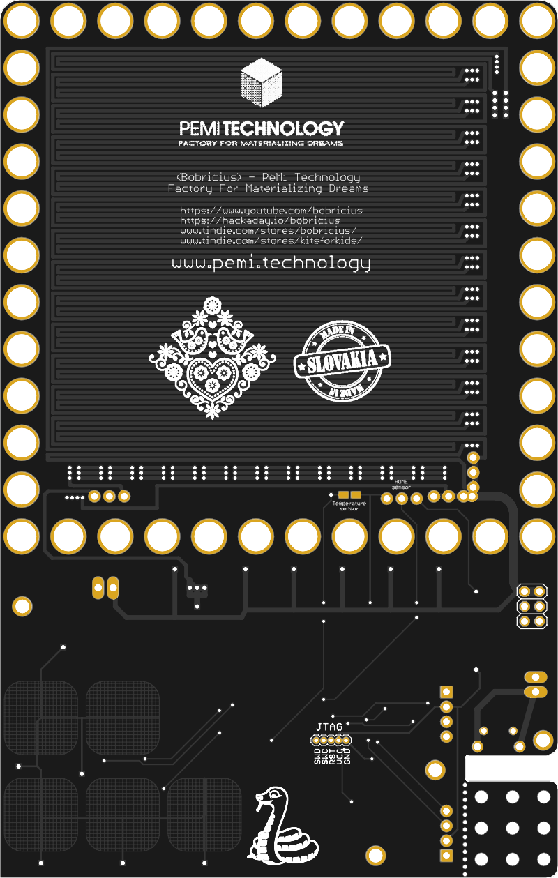
 bobricius
Hackaday article about this project https://hackaday.com/2018/05/22/smiling-robot-moves-without-wires/
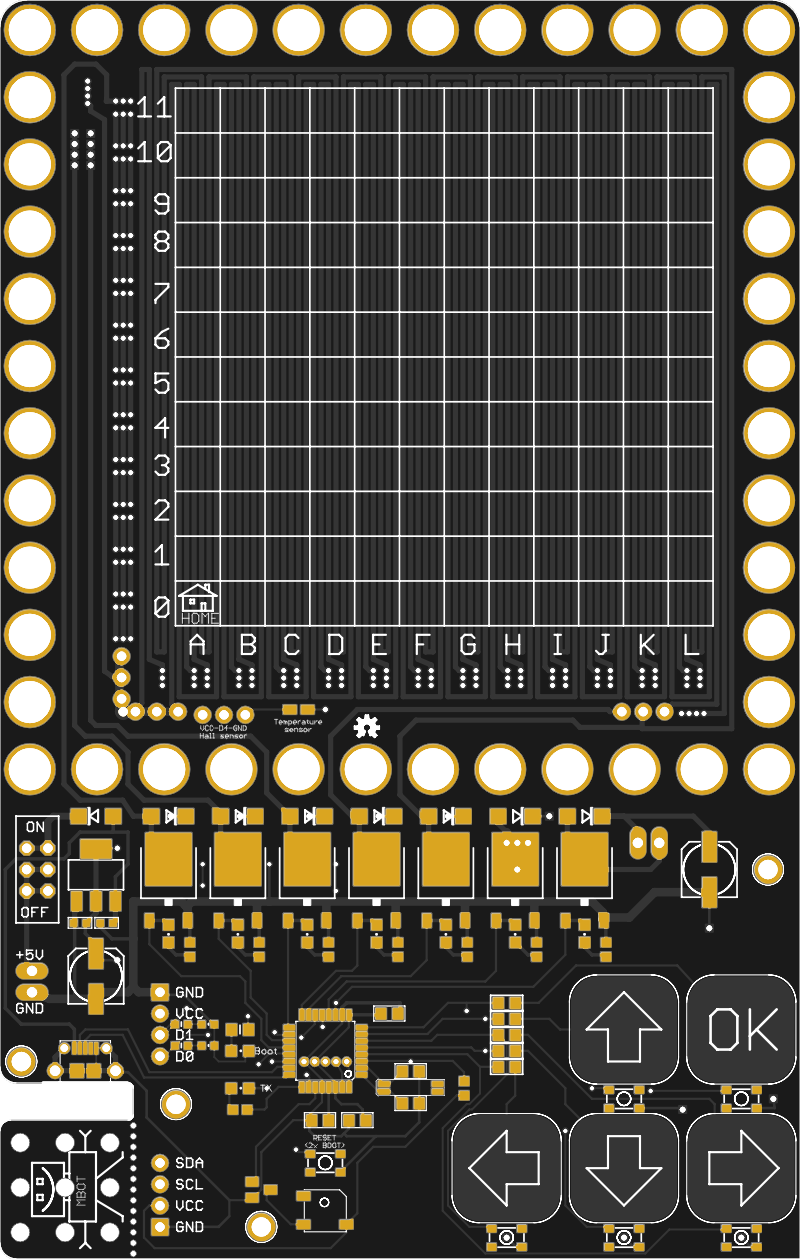
2019 - touch control
Button control
This prototype is designed with atmega328 but I thinking about SAMD21
( 3 ways for programming Arduino, Circuitpython, Makerscode)
At first sight it is very simple but I have doubt, there is absolute no other videos, no similar projects
why? where is problem?
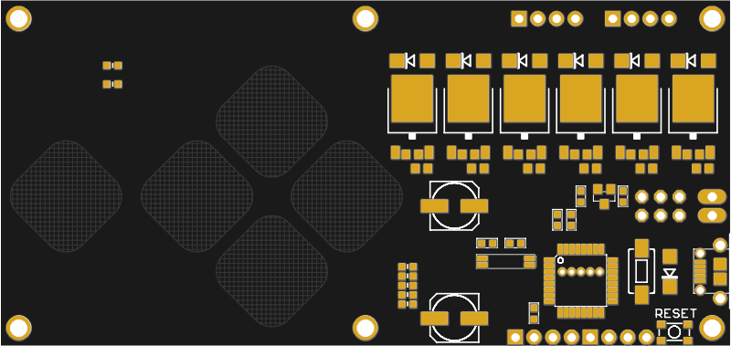
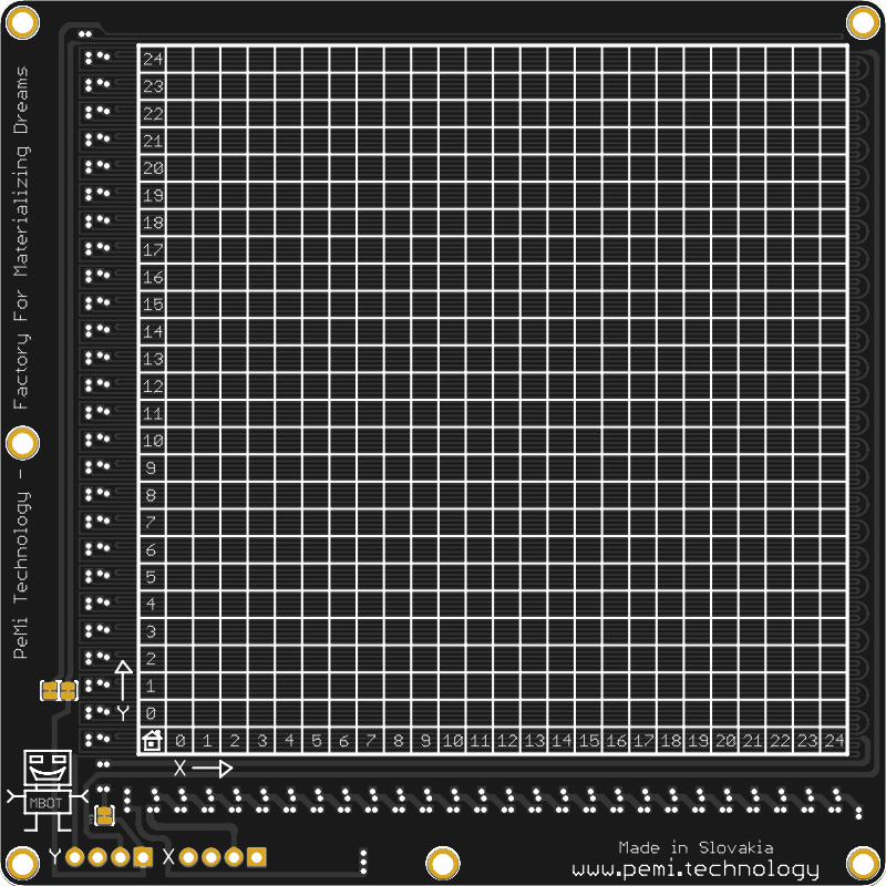
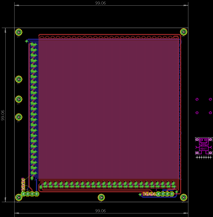
Board is designed as 3 phase linear coils switched with mosfets
What next?
TO DO:
- NFC comunication with bot ?
- feedback, where is wall, object
- manipulation with objects, make gripper?
- home position sensor
- rotation corner
I am very impressed with this video


 Ruediger F. Loeckenhoff
 Adam Mansour
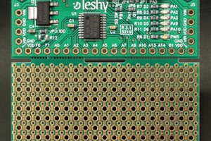
 fruchti
 Leandro
how to solve the heat problem