 Quinn
QuinnThere are a number of variations in wiring based on what parts of a system are installed, as well as just how it is installed, but we can sufficiently generalize.
Wires come into the thermostat from the HVAC system. There is one wire for each control element, such as heat, cool, and fan. There is at least one additional wire to serve as the return. There may be multiple return wires, with separate ones for each element, or they may be combined. To turn on the fan, the thermostat connects the fan wire to the return wire. This is usually a switch or relay contacts. The same applies to heating, simply connect the heat wire to the [corresponding] return wire. Older mechanical thermostats simply used tilt switches mounted on bi-metalic coils to accomplish this.
It is because of this simple control method that this module can be wired in parallel to any existing thermostat. It will function simply as parallel switches; either one closed will active the system. The module will only be configured to control the fan circuit. The module can further monitor the voltage on the control wires to determine if the thermostat has switched on.
In block diagram form of the entire system, there is a 24vac output transformer which feeds power into relays which control the heat/cool/fan(white traces below). The other side of those relays go to the thermostat and make up the associated control lines(black traces below). The return line from the thermostat connects to back to the transformer to complete the circuit(red traces below). Here is a block diagram of the most common system from this link showing the switches in the thermostat, the transformer, and blocks for the heat/cool/fan relays:
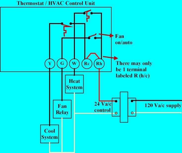
The control wires are commonly labeled as such:
- Y - Cool
- G - Fan
- W - Heat
- Rh - 24VAC for heat
- Rc - 24VAC for cool
- C - Common 24VAC
(Rh and Rc may be combined as simply R if the same transformer is used for both heating and cooling circuits)
These are all shown in the above picture. The white line on the bottom(24V side, not 120V) is the "C" wire. Note that this is an illustrative picture, and does not represent all the variations used in practice.
Discussions
Become a Hackaday.io Member
Create an account to leave a comment. Already have an account? Log In.