 Andy Osusky
Solar Panels And Waterproof Hatches
The solar panels are glued with silicone and two of them are secured with screws.
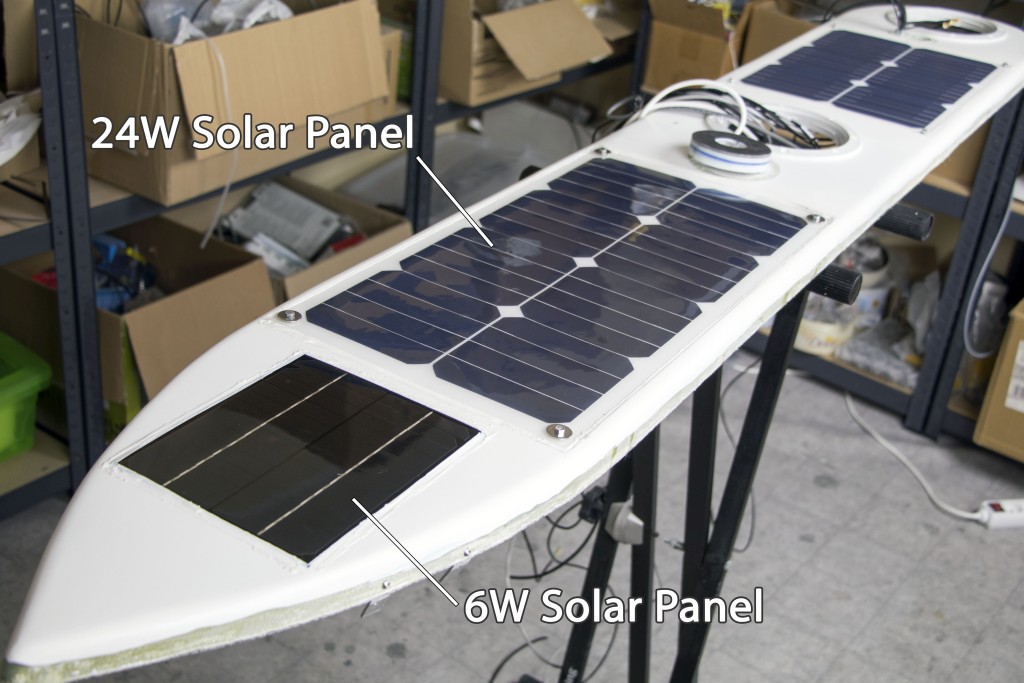


The original connector on the solar panel was not IP68 waterproof. I removed the connector, soldered a new cable to the pads, glued a laser-cut acrylic piece with silicone and potted the wire connections with epoxy.
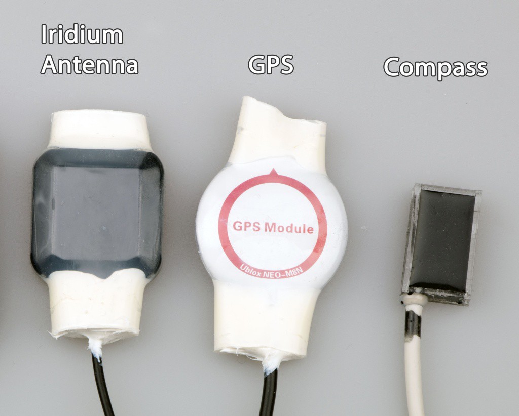
The first three modules in the picture are waterproofed with a heatshrink and silicone. The compass is potted in a heat-conductive epoxy.
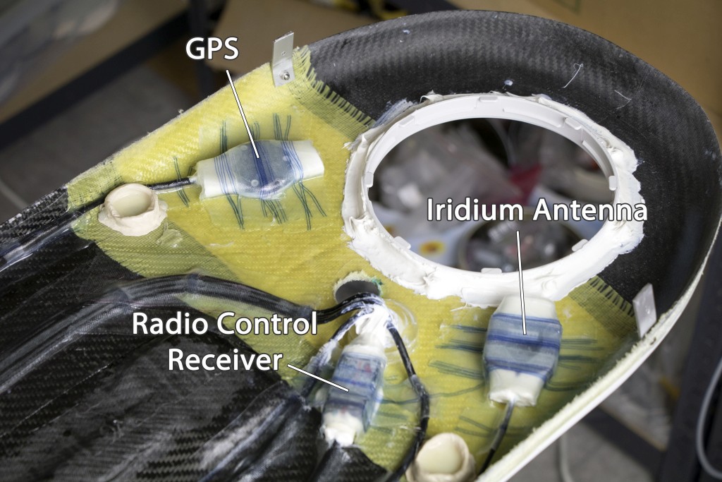
The modules are firmly attached to the deck with a fiberglass tape. I suppose they won't need to be replaced for the lifetime of the boat. The cables are also secured.

All holes for the screws and cables are potted with epoxy. This is the most reliable sealing method, much better than silicone.
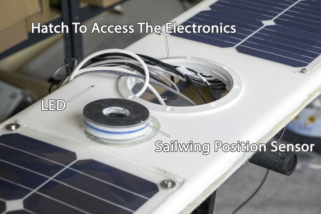
Sailwing Position Sensor
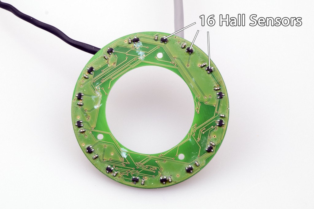
There will be 16 Hall sensors around the mast which will track a magnet mounted at the bottom of the sailwing. The accuracy is 360 / 32 = 11 degrees or even better with some calibration.
There is a small CPU that switches between the Hall sensors, crunches the data and sends the result through a serial cable to the main controller. The second cable is for programming.
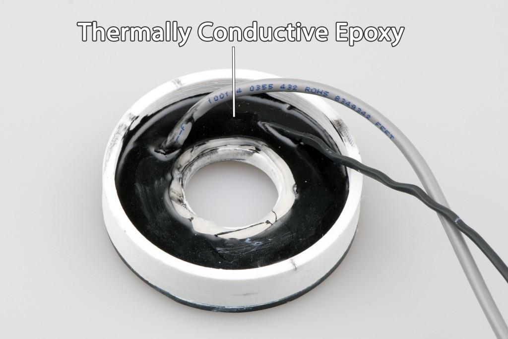
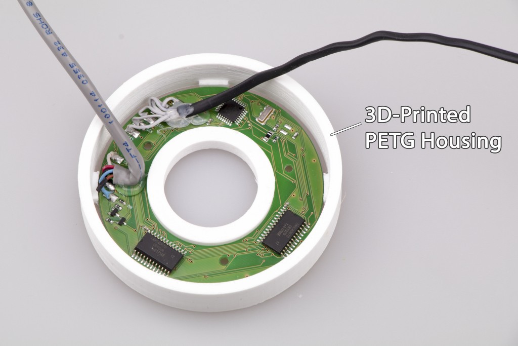
The PCB is potted in a thermally conductive epoxy, making it perfectly waterproof and shockproof.
The Electronics Inside The Sailwing
As the sailwing is free-rotating, I had to build a crazy concept where there is no electrical connection between the sailwing and the hull. A cable could easily overtwist and break. Waterproof rotary connectors have a high friction and unknown life span. All the power needed for the actuator comes from the small solar panels mounted on the sailwing. The actuator is controlled wirelessly by commands transmitted from inside the hull.
All the PCBs are waterproofed with a heatshrink and silicone, so accidental water leakage into the sailwing won't cause any issues. Before the real mission, I will waterproof the batteries and fill the empty space with bubble wrap.
There are two 6.6V / 1100mAh batteries connected in series that are charged by the solar panels. The total current consumption is only 9.5mA. If the actuator adjusts the flap 3-4 times per hour, it will add 1mA to the average consumption. The batteries can provide enough power for 4-5 days without any sunlight if the controller is constantly listening for commands. During a long series of cloudy days, the controller will enter power-saving mode which will increase the response time.
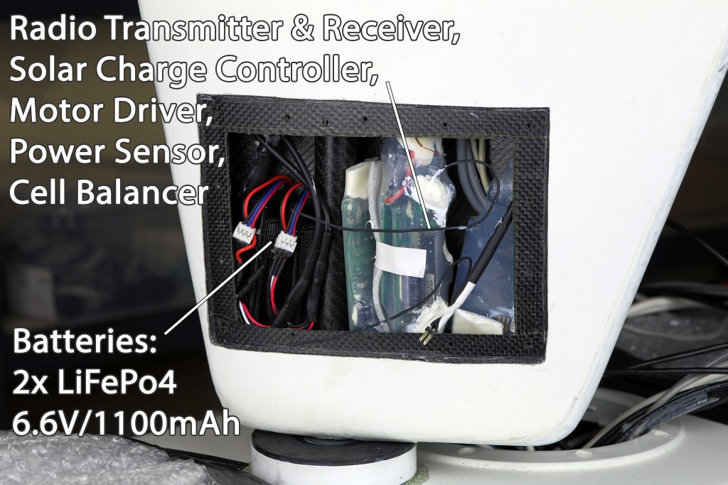
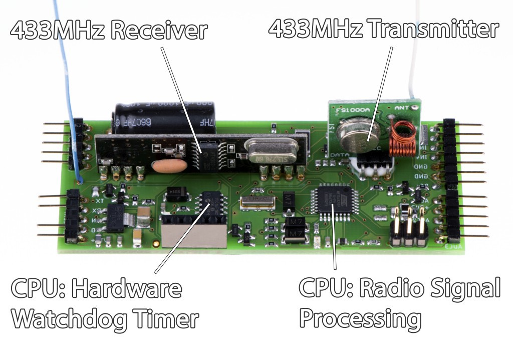
The controller processes the data from the radio receiver, checks for any errors, controls the actuator position and transmits a response which may include the battery state, solar power, etc. The radio link uses a low-level protocol to eliminate connectivity issues. The main controller inside the hull will repeatedly transmit commands until it receives the response from the sailwing.
In theory, carbon fiber blocks radio signals, but I have tested the controller inside the sailwing and it works.
About the hardware watchdog:
From my experience, a dedicated low-power microcontroller that resets the main controller can solve more potential issues than just a built-in watchdog timer.
The Electronics Inside The Hull
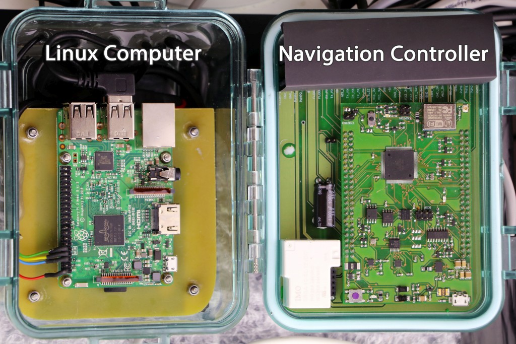
The electronics is enclosed in a waterproof polycarbonate case. The Linux computer on the left (Raspberry Pi) will record short videos or take pictures from USB camera and store them on an SD card. It may also send compressed pictures through a satellite modem on request. Because Raspberry Pi is power hungry, it will be switched on only when needed.
The custom-built Navigation Controller on the right has been published in another project log a while ago.
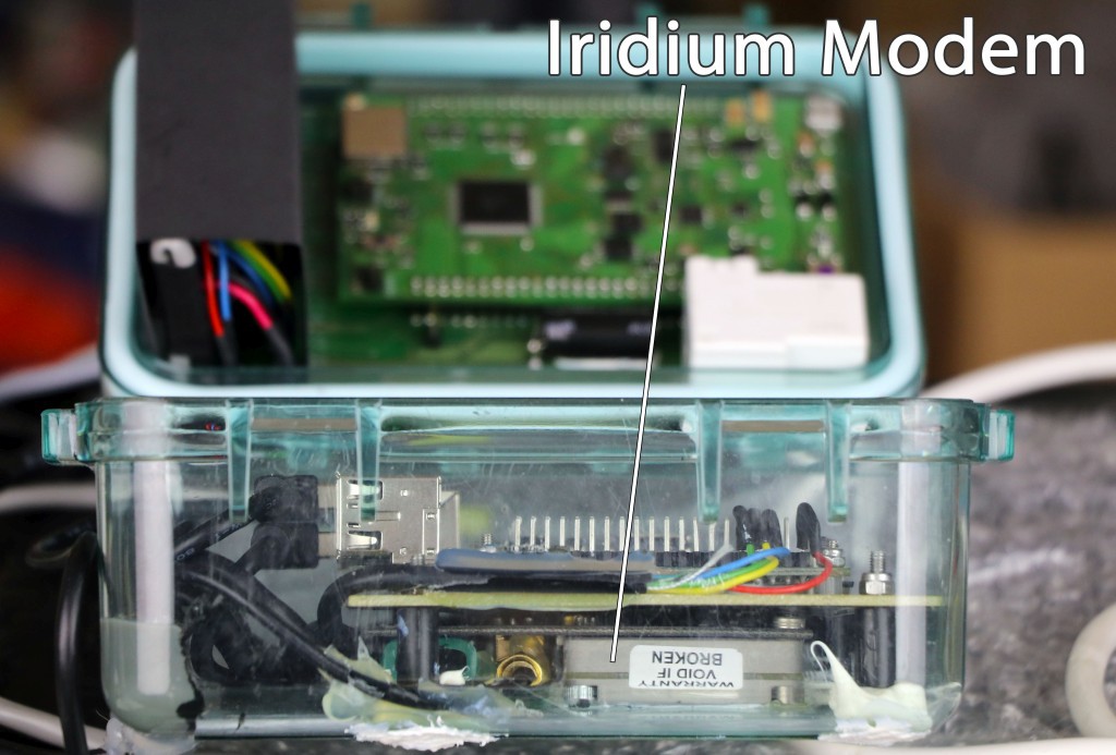
The Iridium satellite modem (RockBlock) is for transmitting short text messages like GPS position, battery voltage, power output of individual solar panels, data from different sensors, etc.
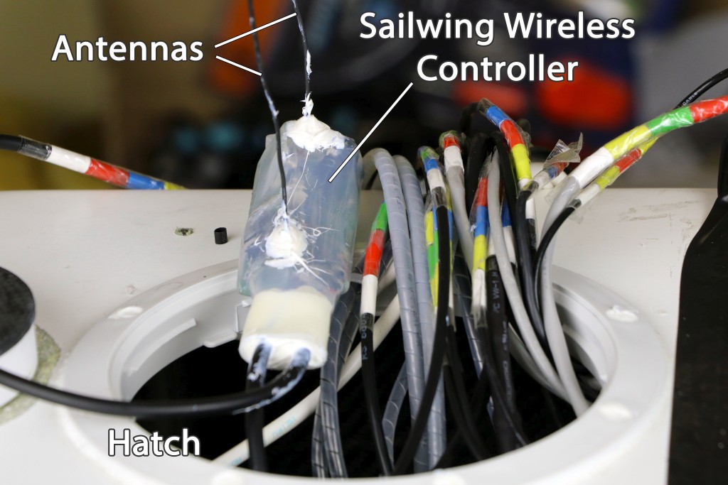
The polycarbonate case can be easily pulled out through the hatch in order to access the electronics.
The sailwing wireless controller will be located somewhere inside the hull as close to the sailwing as possible. It's waterproofed with a heatshrink and silicone.
I find the color codes on the cables very useful to prevent wiring errors.
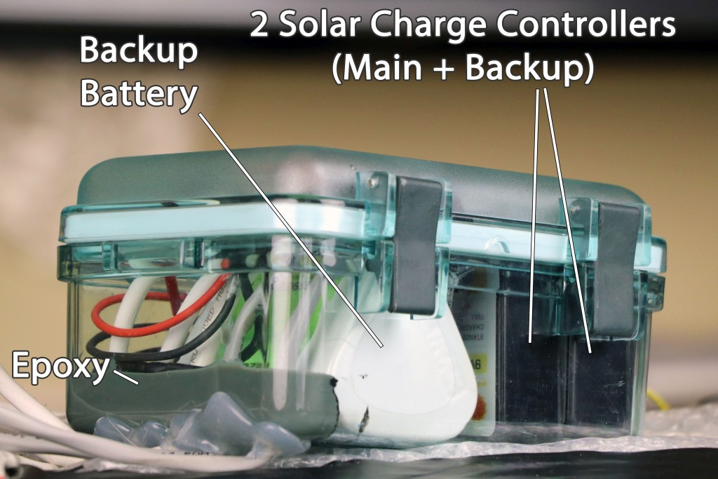
The second polycarbonate case protects a backup battery (LiFePo4 9.6V / 2500mAh) that's independently charged by a secondary solar charge controller. The backup battery will provide power for the secondary tracker that will keep transmitting the boat location even if the main power source fails.
The epoxy-sealed cable pass-through makes the housing perfectly waterproof for full submersion.

The waterproof connectors are used as switches to disconnect all power sources from the electronics.
The solar power sensor is a PCB potted in a thermally conductive epoxy. Its function is measuring power output of individual solar panels and reporting the data to the main controller. It must be kept outside the polycarbonate housing as the blocking diodes may get pretty hot. More details on GitHub: https://github.com/OpenTransat/PowerSensor
Discussions
Become a Hackaday.io Member
Create an account to leave a comment. Already have an account? Log In.