 mikrotron
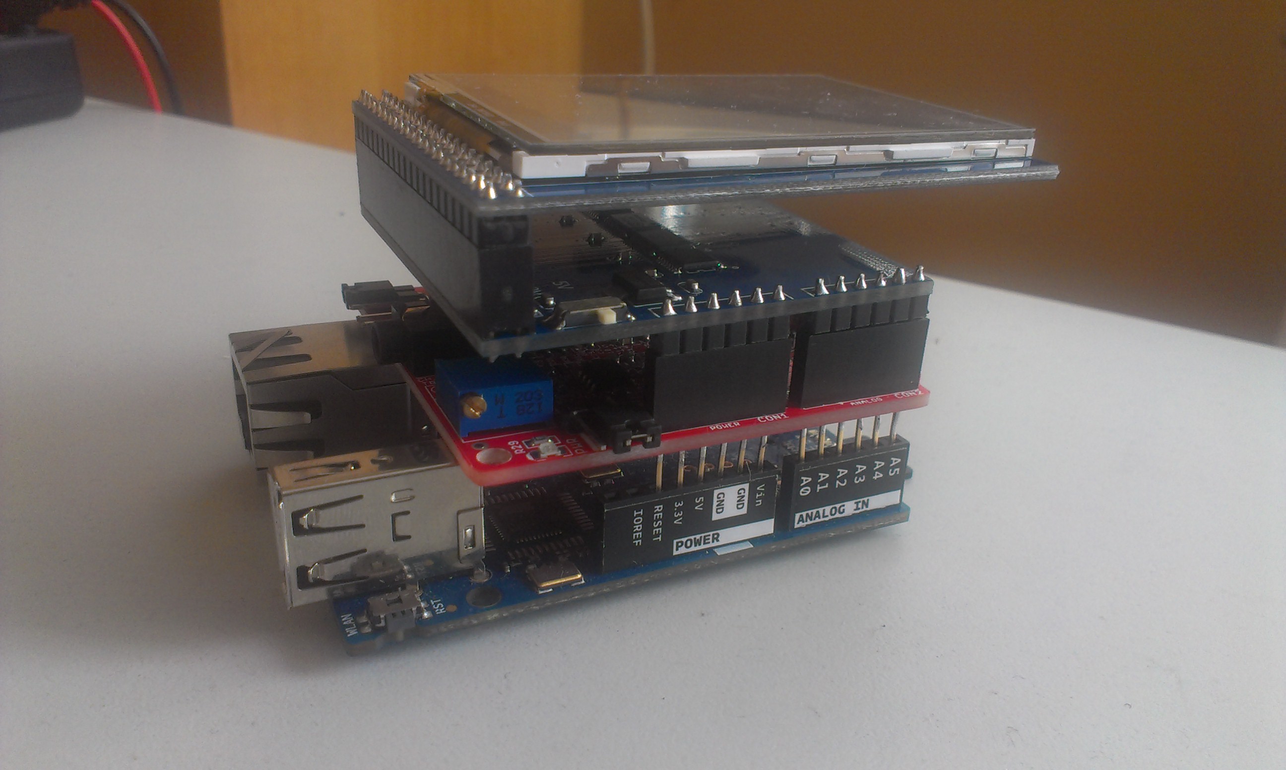
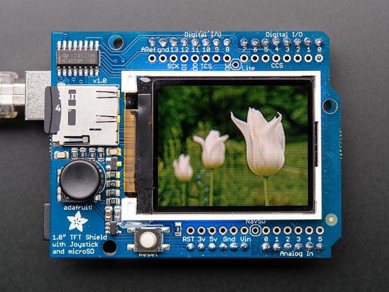
Building an Arduino ECG is piece of cake:
plug in the shield, plug in electrodes, plug USB cable to PC.
And then what?
Well, then comes the hard part:
1) You get some signals; they are dirty
2) So you need to clean them up
3) Can you read them? Unlikely; so you need some way to send them to your doctor
There's no free software to read, filter and save the data.
That is, there was no free software till we wrote it;)
Ah by the way, we also designed a nice 3d-printed enclosure for it.
All open source: https://github.com/mikrotron-zg/srcotron

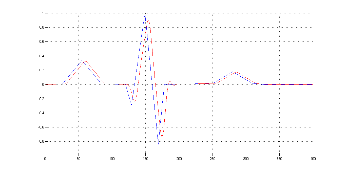
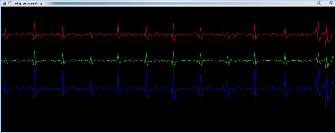 Seems like my heart worked:)
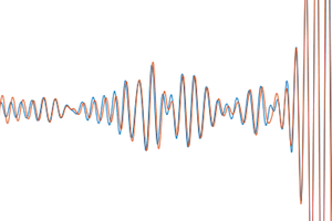
 Ben Hencke
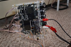
 tshen2
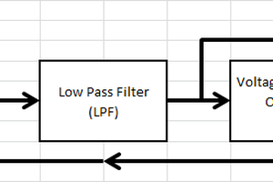
 agp.cooper
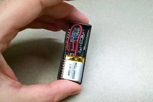
 Eric Herbers