 Jorj Bauer
All in all, I did make progress over the weekend! I also destroyed a few things along the way.
Starting from where I left off in Phase 7: thinking about controlling the Hoverboard controller directly, I want a 3.3v logic level serial interface, so I was thinking about the Moteino. That would move me to an RFM69 instead of the RFM12b I'd used for wireless before (which I destroyed in Phase 7 by passing +36v in to one of its pins!). Which would mean the transmitter also needs to be converted. It also means I'd be able to reprogram both the remote and the Dalek-side Moteino over RF, instead of having to open them up. Okay, I'm sold.
Let's start by opening up the old remote. I've lost most of the screws from opening and closing it so many times. There's a lot of hot melt glue holding it all together.
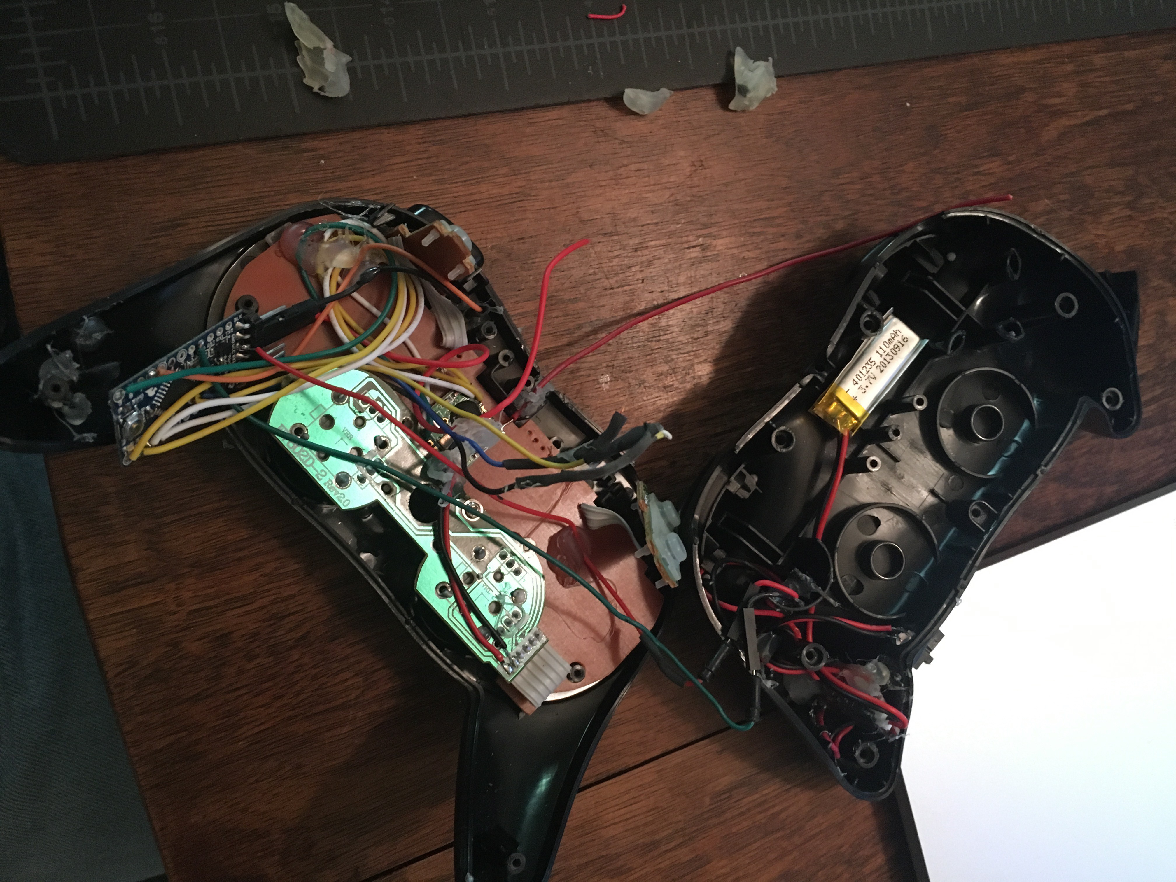
In the left half is an Arduino Pro Mini 3.3v. Most of the wires coming off of it go to the RFM12B, glued down near the center. A few go to the I2C lines. Two run to the right half, where all of the power circuitry sits - a 110mAh LiPo battery with a SparkFun PowerCell for charging it. There's also a sliding power switch hiding near the left hand grip.
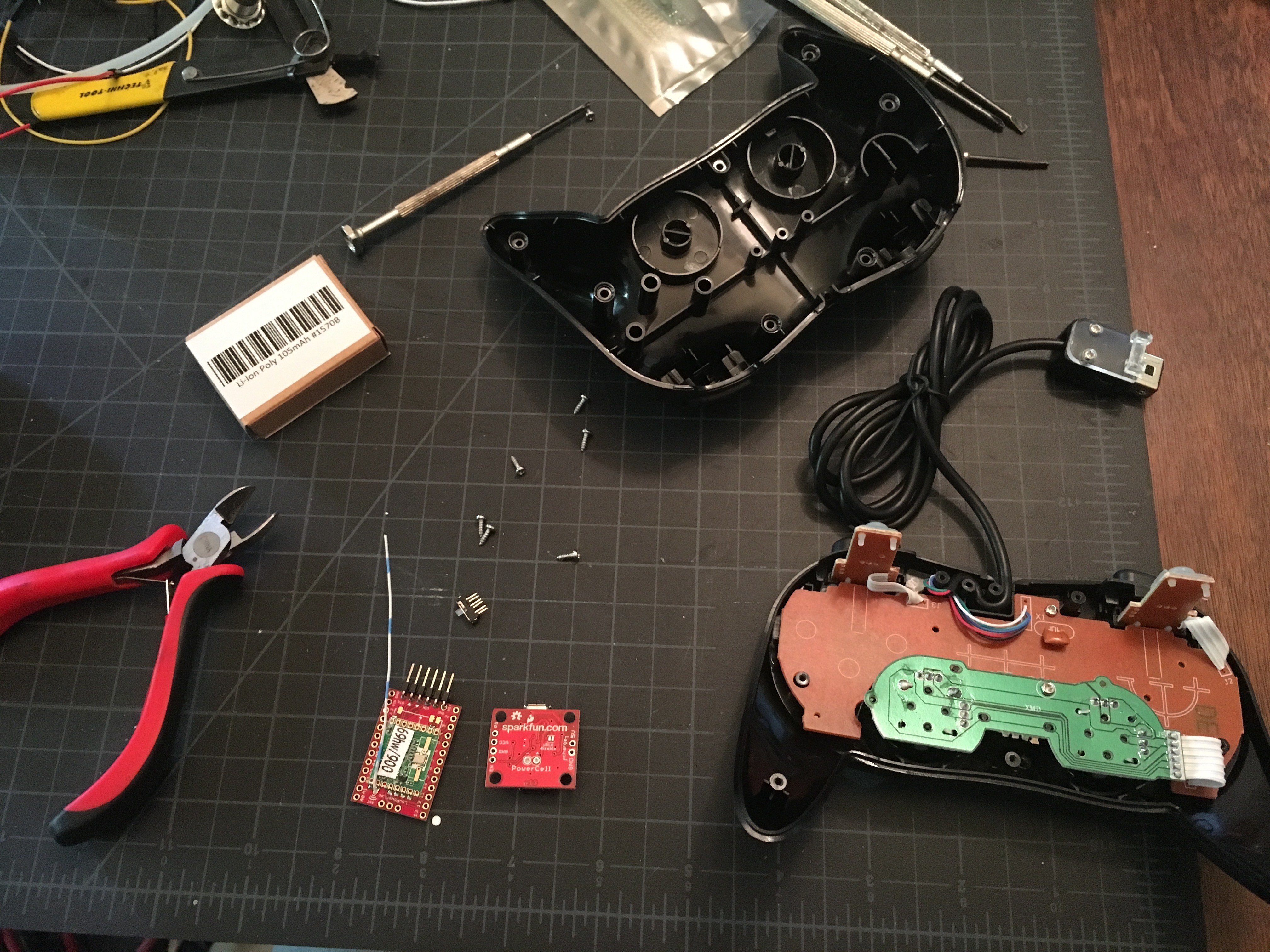
I bought another cheap knock-off controller for the rebuild. Here it is with the parts all waiting for assembly:
Cutting off the connector, wiring the Moteino in to the I2C lines:
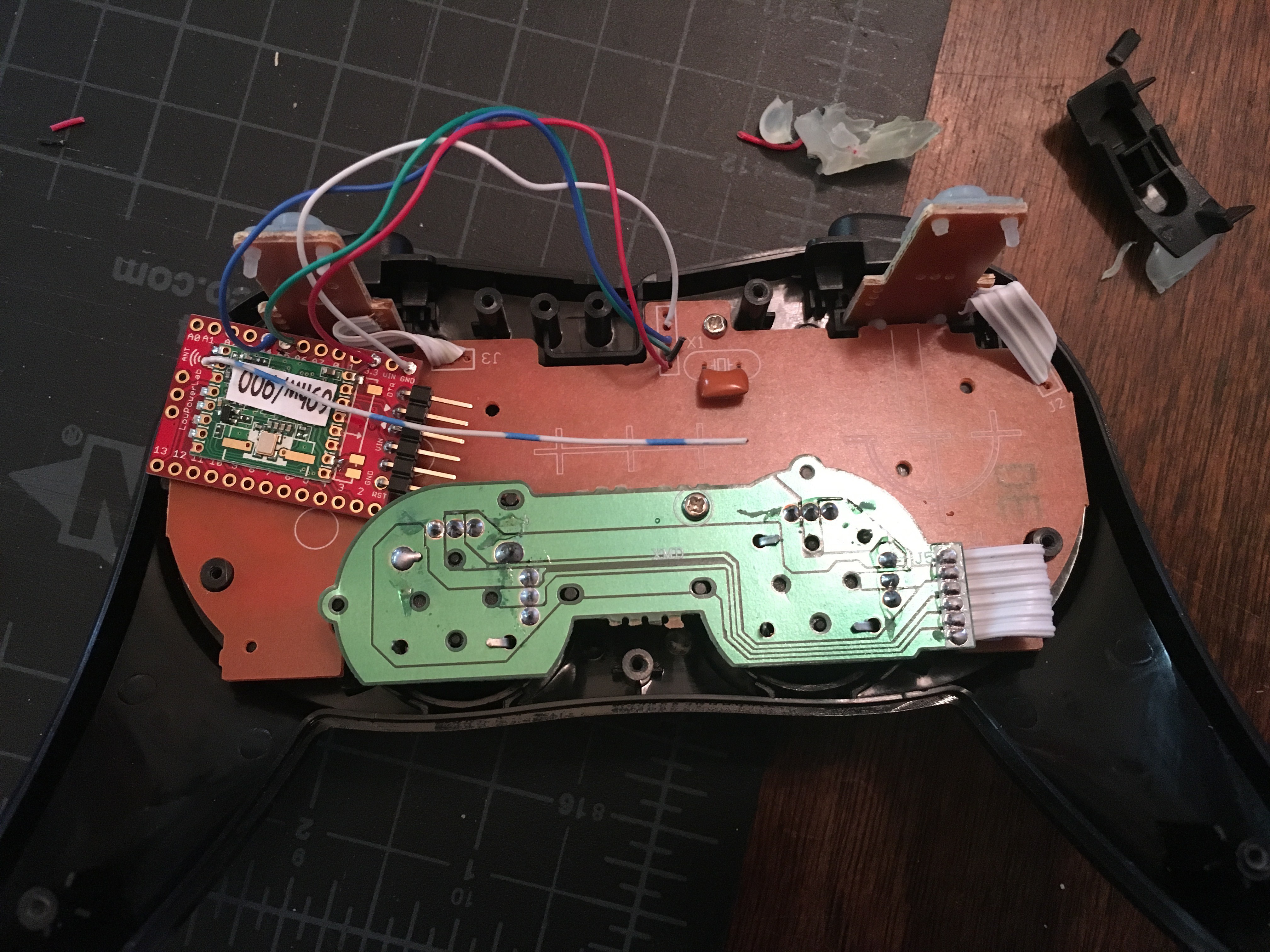
Damn, that's so much simpler. Add the two power lines to the other half, put in the power circuitry, add an LED and close it up. Sweet.
The power switch is now recessed. It's harder to activate, but it's not in your way when you hold the controller. It does foul the down path of the left joystick a little, but that's acceptable for the moment. There's no longer an exposed antenna wire to be broken off, and the wireless programming is really a boon.
So let's move to the main controller board from the Hoverboard!
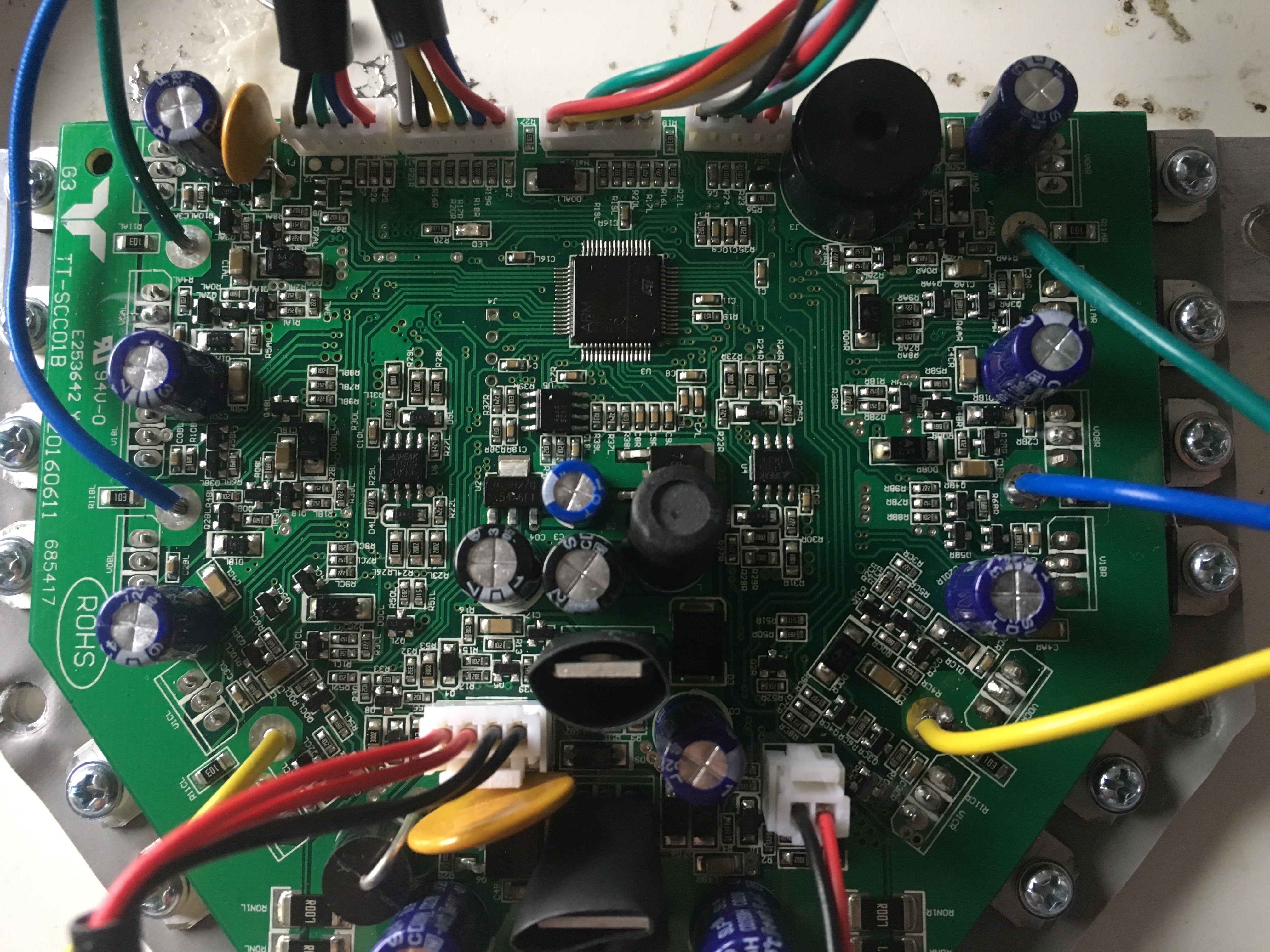
First off: there's a momentary push button (the lower-right red and black connector) that turns the board on and off. I'm going to need to control that from the Moteino inside the Dalek, so I wired that up to a relay.
Second: I need to communicate to this as if I'm one of the tilt-sensor boards. The Cortex M3 on this board runs some magical program that reads what the two tilt-sensor boards spit out, and drives the motors appropriately.
I started with [Drew Dibble]'s work, programming the Moteino to send frames like he did. Nothing happened, so I dug out my Logic to snoop. And it's different. It's at 53156 baud, which is differently weird. I think this, and Drew's 26315 - which should be 26316, probably, due to rounding - are documented alternate CAN bus speeds. If I read all that documentation correctly. If I had to guess, I might think that someone intended for this to be CAN (the M3 on this board is documented as having a CAN bus interface) but then backed out for some reason? No idea.
The protocol is still 9/N/1 serial, but the data being passed is different. Here's one frame:
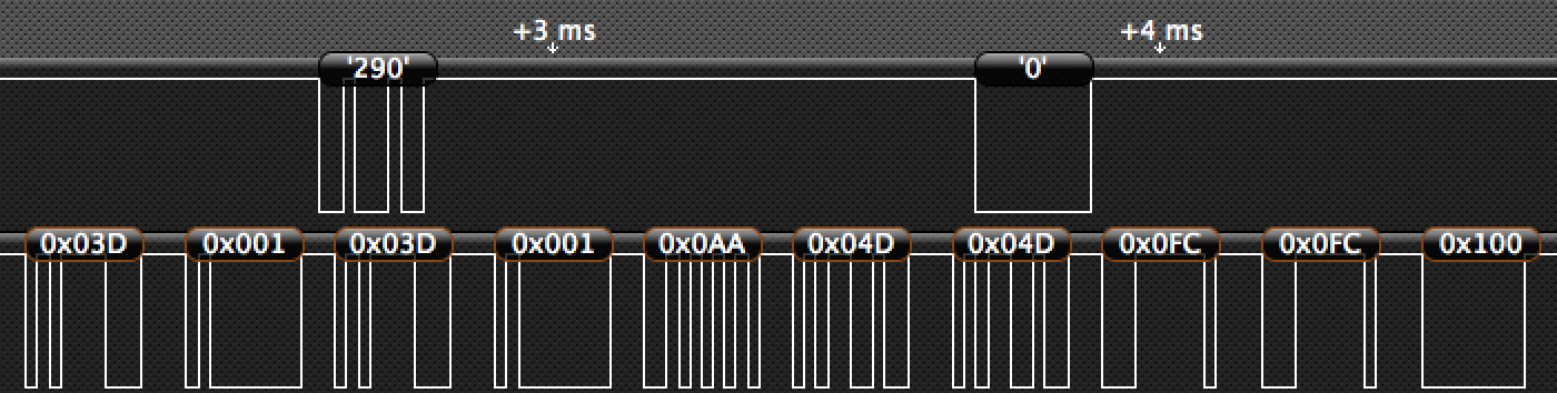
The other item of note here is the communication from the main board - the 290 / 0 on the top trace. I can use that to see whether or not the main board is turned on. Polling once every couple of seconds, if I don't see communication coming from the main board, I'll momentarily power up the relay to press the power button. Works well enough for a hack on a hack.
So, leaving one tilt sensor board in place and substituting my own data for the other one: if I send (angle) (angle) (0x55) (0x40) (0x40) (0x00) (0x00) (0x100) - I'm able to control the motor reliably. As long as, like Drew's setup, I started transmitting soon after power-on, and kept transmitting. I spent some time figuring out how long I could draw out my transmissions and retain control, important because I intended to drive two serial communications simultaneously, and they'd be sent one after the other. It works reliably up to about 250 ms, which is fantastic; plenty of time for other communication. I refactored a 9-bit serial library so be send-only (no receive); set up the code to control both simultaneously, but left it connected to just one of the two motor inputs; and it still worked really well while updating both serial outputs (one still disconnected) once every 100 ms or so.
This is about where I got to late Friday night, and I thought I was pretty close to done! Boy, was I wrong. Saturday morning, I connected the second input, and here's where things got wonky.
When driving the right motor with the Moteino, and one of the original tilt sensors connected to the left motor, I had full control. When I drove both left and right motors from the Moteino, if I drove either motor anywhere over about a quarter speed, the motor would go runaway: speed up to max speed, controller board piezo speaker starts angrily beeping, no way to stop it except to pull the power.
The obvious thing to do here is to look at what the left tilt board is sending while I'm driving the right motor myself. So I grab the Logic, start connecting it, and *POP* - no idea what I shorted, where or how, but I blew out my Logic. Crap. New Logic8 ordered to replace my original Logic: check. At least it's an upgrade of sorts.
I spent a few hours playing with the protocol, trying to figure out what it was doing. Adding safety features. Rigging up 9-bit serial readers to see if I could reliably receive and relay the data. All in vain. With evening fast approaching, I've got no reliable way to drive both motors at the same time. This makes me really nervous; I don't need a runaway Dalek at a crowded convention. So I put the battery on the original controller to charge it while I looked for new controllers.
Now, there are *lots* of brushless, reversible, 36v controllers out there on the Internet. And almost all of them come from China, which would be delivered too close to my deadline. But I did eventually find one used controller on eBay, which I snapped up quick as can be - and then, after an hour or so of hunting, two new ones at electricscooterparts.com that should be here in the next week or so. Which is where I bought the wrong (brushed) ones in the first place. Hmm.
Okay, back to work then - I hook the battery back up to my new power distribution harness, and nothing works. Which I eventually find is because my 36-to-12v buck converter has noticed that I'm jamming 41v out of the freshly-charged LiPo battery, and therefore it let out its magic smoke. What. An. Idiot.
Which makes me think - I know nothing about these motor controllers. Is the one I just bought going to be similarly finicky? They also sell a "36v/48v" version of that controller, which I presume auto-senses. So I place YET ANOTHER order for two controllers, canceling the 36v-only ones.
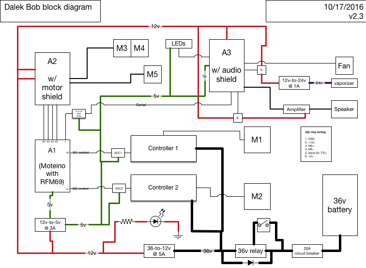
Which brings me to this updated block diagram.
I spent Sunday working with one unidirectional brushless controller, just proving that I've got it under control: with the help of an MCP4921 12-bit Digital-to-Analog I2C chip that I had lying around, I fed nice clean analog DC in to the controller, and it didn't buck at all. Perfect control, just in one direction. I would have wired up both motors but I don't have another 4921 lying around, so this will also have to wait until more arrive...
Once again, waiting for parts. :/
Discussions
Become a Hackaday.io Member
Create an account to leave a comment. Already have an account? Log In.