 Jorj Bauer
That was the shortest Long Wait *ever*.
Enough of the hyperbolic statements about delays! The controllers arrived a day early, so last night was filled with interactions like this.
The slight scraping noise is one of the wheels brushing against the cardboard box; nothing I'm worried about. Crappy rushed woodworking aside, I'm pretty happy with this. (And damn, that bad cut is going to bug me until I fix it. I've slated that for mid-week next week for reasons of logistics but I'm not sure I can stand waiting that long...)
That was controlled by the new remote, running through the Moteino (on the protoboard) which is running both motors from one Analog-to-Digital converter (the only one I have at the moment). The rightmost flashing light is debugging code that's toggling the onboard LED whenever it gets a "G" pulse (telling the motors to run for a short while), and the other flashing LED is on an RS232 USB adapter (the board's sending serial output for debugging while I tuned the ADC).
There are a few really ... interesting ... behaviors of the new controllers.
There's a reverse line that, when pulled to ground, tells the controller to run the motor backwards. So I set up the Moteino with a pin to do so, and it works. It looks like, when running backward, the controller will only run at about 2/3 speed.
Now, that's got to be a safety feature. I wish I could disable it. And I may very well open up one of the controllers to try, if I have extra time on the project. If it's anything like the last (cheap, eBay, low-quality) controller I disasembled, I'm going to find that it's all embedded firmware controlling this with no way to disable this behavior. I can live with it, though; I thought about making it run slower when going backward anyway. It just slightly screws up my vector calculations when turning - but I can probably measure the difference and compensate if I need to.
This controller has three "speeds" you can set - high, medium, and low. So I put it in to "medium" mode, and found that when you start rolling the wheel in "medium" mode, it actually turns backward a bit before going forward. Not really nice. I couldn't find any way around this (slower ramp-up, faster ramp-up, jumping right to a higher throttle value). So I won't be using that feature; easy enough to avoid and just implement myself. In fact, it's already implemented - the first two spins of the wheels in the video are forward and backward in "slow" mode before I throw it in to "fast" mode and spin forward a few times at full throttle, then coming down to about half for a second, before finally stopping.
Both of those I can deal with. But the third is trickier.
The reason I don't throw the controller in to reverse while in high speed is that, well, I can't. If the motors are spinning more than (some speed), they won't reverse until they're spinning less than (some perhaps-different speed).
I can see how that would be important. Back EMF, damage to the motors, safety. Yeah yeah. BUT. If it's in the "too fast" state and you try to hit reverse, it doesn't *just* ignore you until the motor is slow enough. It *continues* to ignore you until you stop telling it to move at all.
So the Moteino is going to have to keep an estimate of how fast the motor is going, forward or backward, in order to figure out what's actually happening so that it can reverse.
Fortunately this probably won't be a problem in the real world. The load of actually moving Bob's actual mass should stop the motors pretty quickly and allow for quick reversing. Regardless, I find myself writing code to estimate the current motor speed and to fall off with an estimate of the decay. I forsee lots of testing that will be close to correct, but which I'll want to tune forever. :/
Anyway - now that the controllers are here, I can finally estimate how to mount everything. Here's a mock-up in foam core:
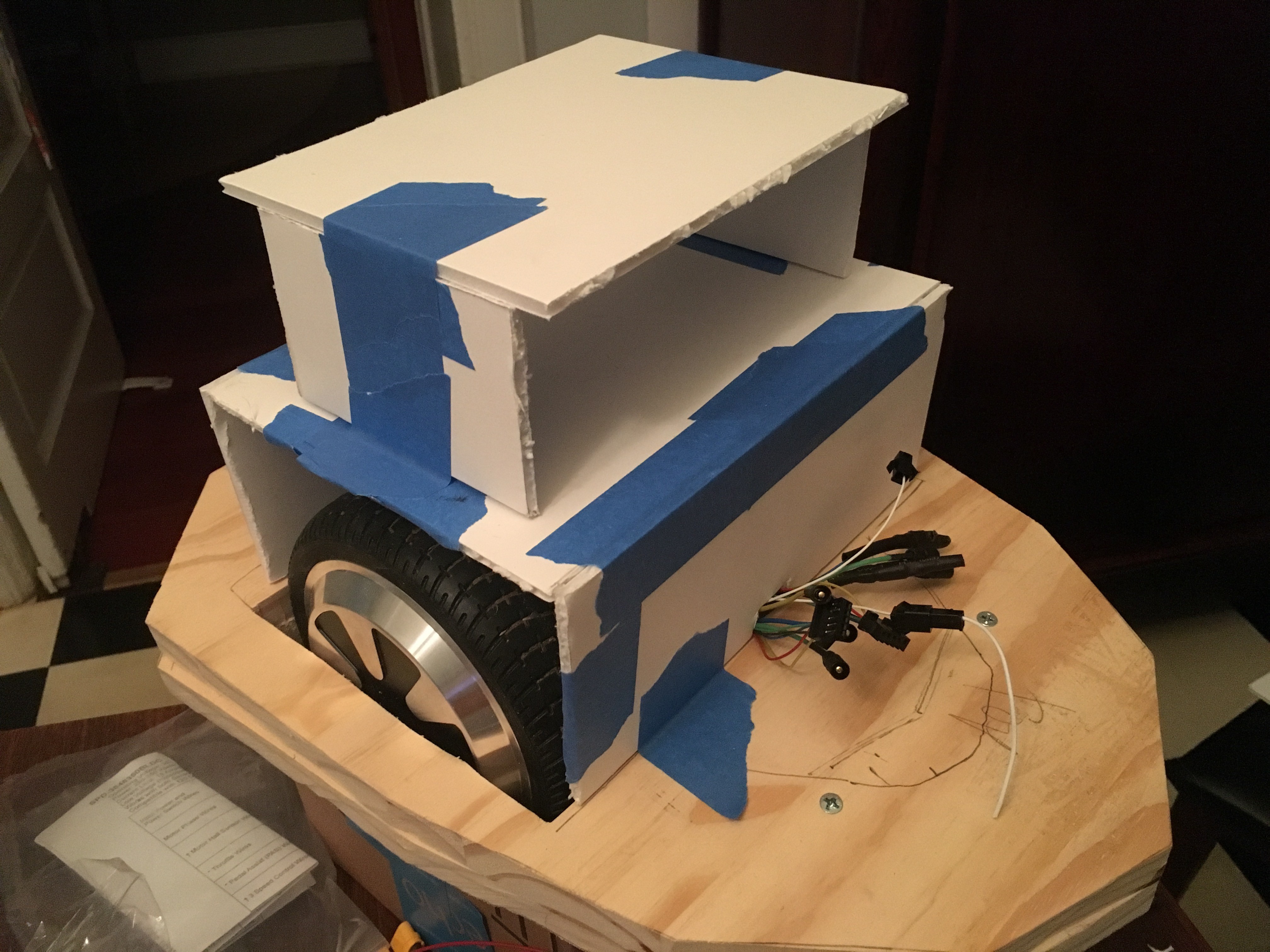
The line drawn on the base is the clearance inside the model. WIth so little space, I can't really mount anything there, unfortunately. I could cut more of the base of the model out and give it a go, I suppose - but I'm more inclined to just go vertical and use up the space I've got.
I also can't fully enclose the wheels, unfortunately. I really wanted to - it would keep water out! - but it's just not going to work. There's almost no side clearance beyond the tires inside the model; I've really pushed this as far as possible. Horizontally, at least. I *could* seal the box around the inside sides of the model, but then I wouldn't be able to take it apart to service it. I'm really trying to build this so I can unlatch the motorized base from the rest of the Dalek; unhook a few wires that go to other motors and controllers; and then lift the Dalek off, cleanly and easily. That would leave me with a base that I can drive around independently of the rest of the Dalek which would be really great for testing and demonstration purposes.
So I'm planning on building a rigid luan structure with similar dimensions to what you see in that picture. I'm going to put the battery just over the motors, and enclose the front of that level so that it can't fall out. The two motor controllers have to go all the way up top, which is a little unfortunate. And the battery compartment may shift forward to be more even with the front edge - or perhaps will just be deeper, matching the size of the wheels - giving me more room behind the battery (or behind the two controllers up top) to mount the controller and a relay (which keys power to the motors). The power circuitry I'd like to have mounted vertically on the back plate so I can get to it easily from the back hatch. In paritcular, there's a 20A circuit breaker that I want to be accessible...
Discussions
Become a Hackaday.io Member
Create an account to leave a comment. Already have an account? Log In.