 laurenternes
The project started with the research of an autonomous voice recognition library, that would take care of the audio input stream, and run smoothly on our embedded platform.
Of course we could have used an online service for that (Google,...) but there were 2 main drawbacks:
- the response delay that can vary, and be too long
- the risk that the internet connection shut down
These are unacceptable issues while running on a treadmill ; you don't want to loose control of it...
The ideal library would match all of the following criteria:
- lightweight: the CPU should still have some room for treadmill control
- have a python interface: this is our preferred language
- be open source
- be free charge: we do not have much money :-)
Very soon it turned out that CMU sphinx, and its small sister "pocketsphinx" would fill the bill.
As embedded platform, we just use an Odroid-C1, and made a nice 3D printed case for it.
This platform has plenty of I/O pins, USB ports, ethernet,...
It is just missing bluetooth (note for next platform selection), but we can easily plug in a bluetooth dongle on it. So, we can connect a wireless earplug, and complete our input channel.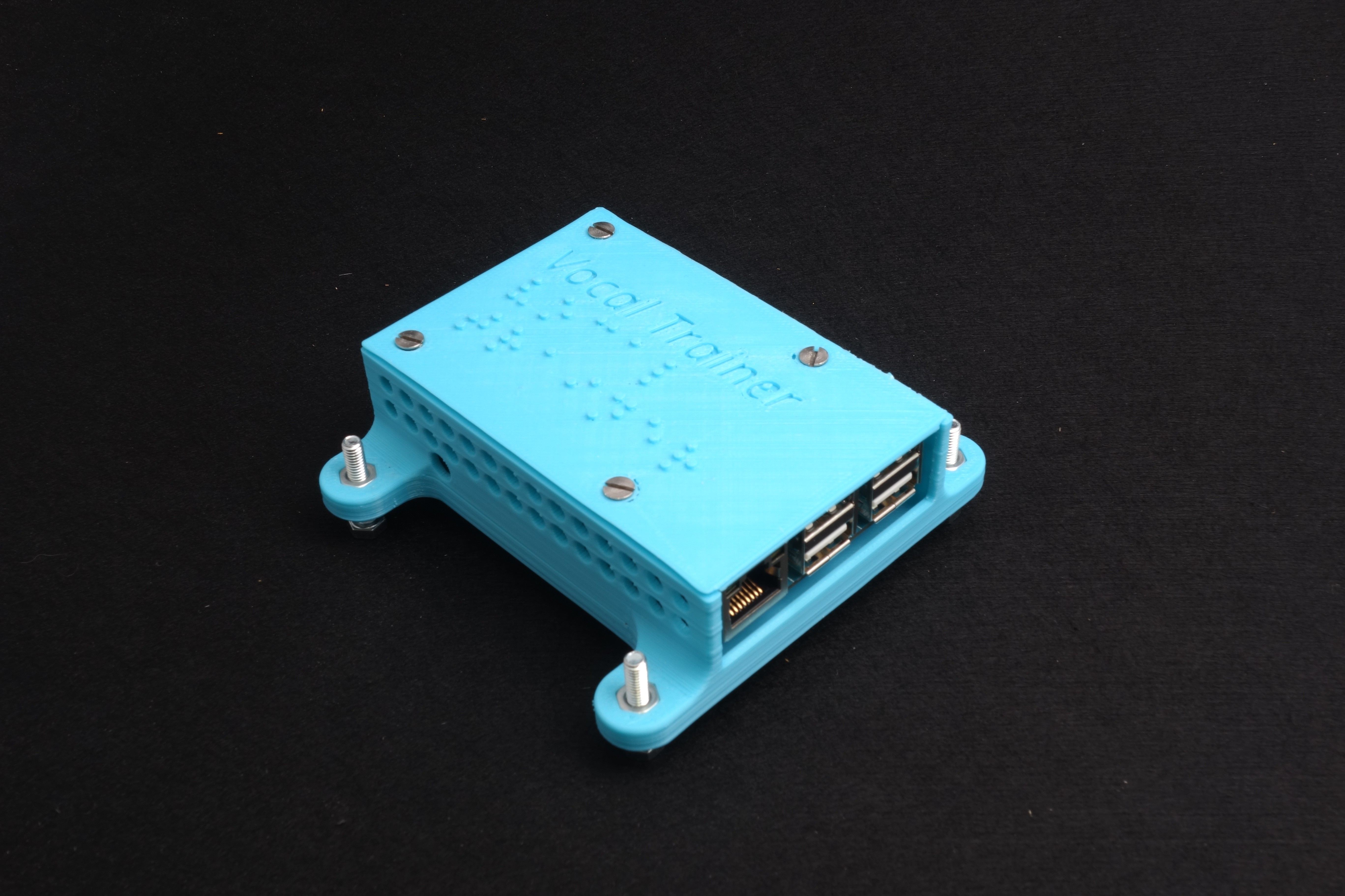
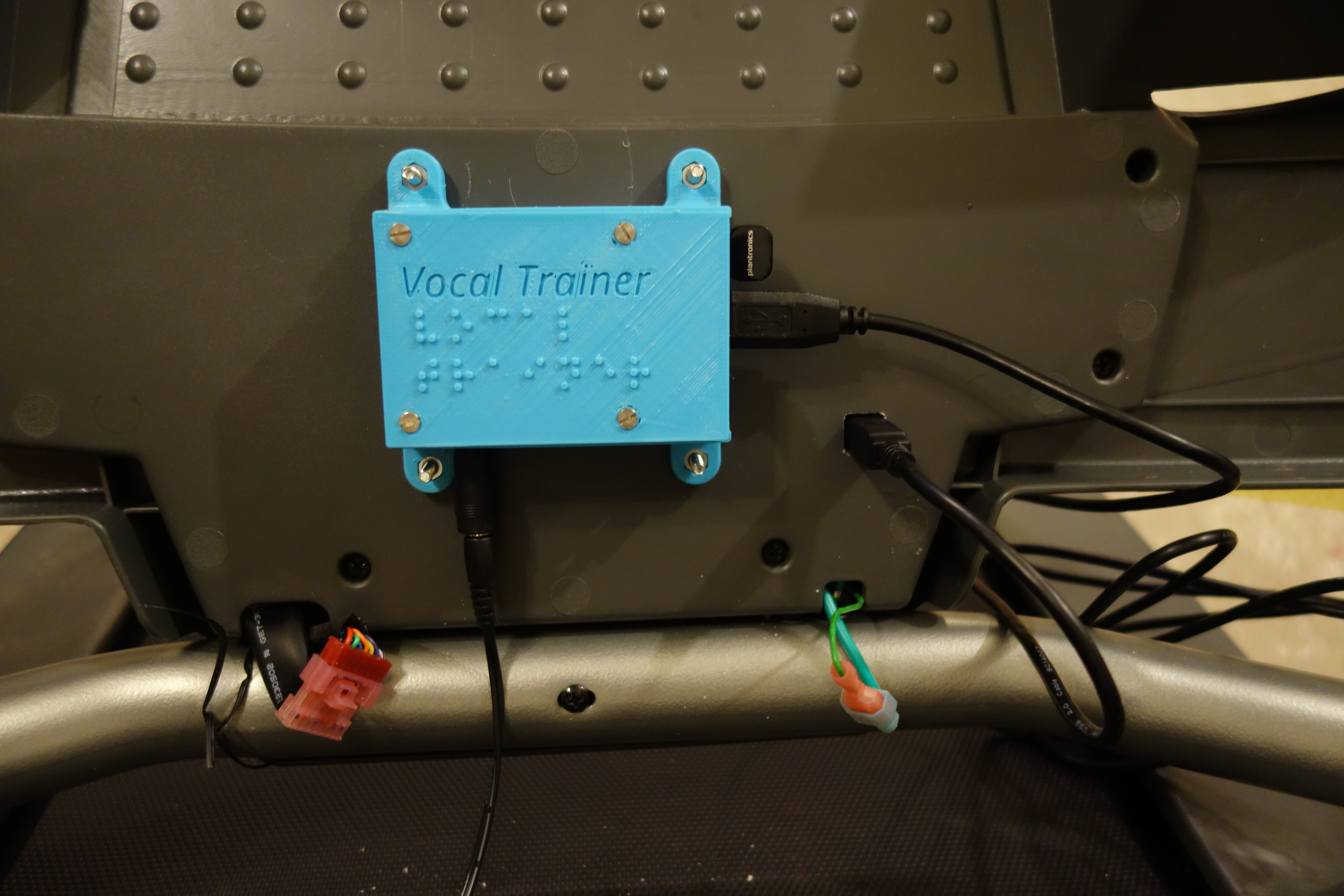
This box will be mounted on the back of the treadmill console.
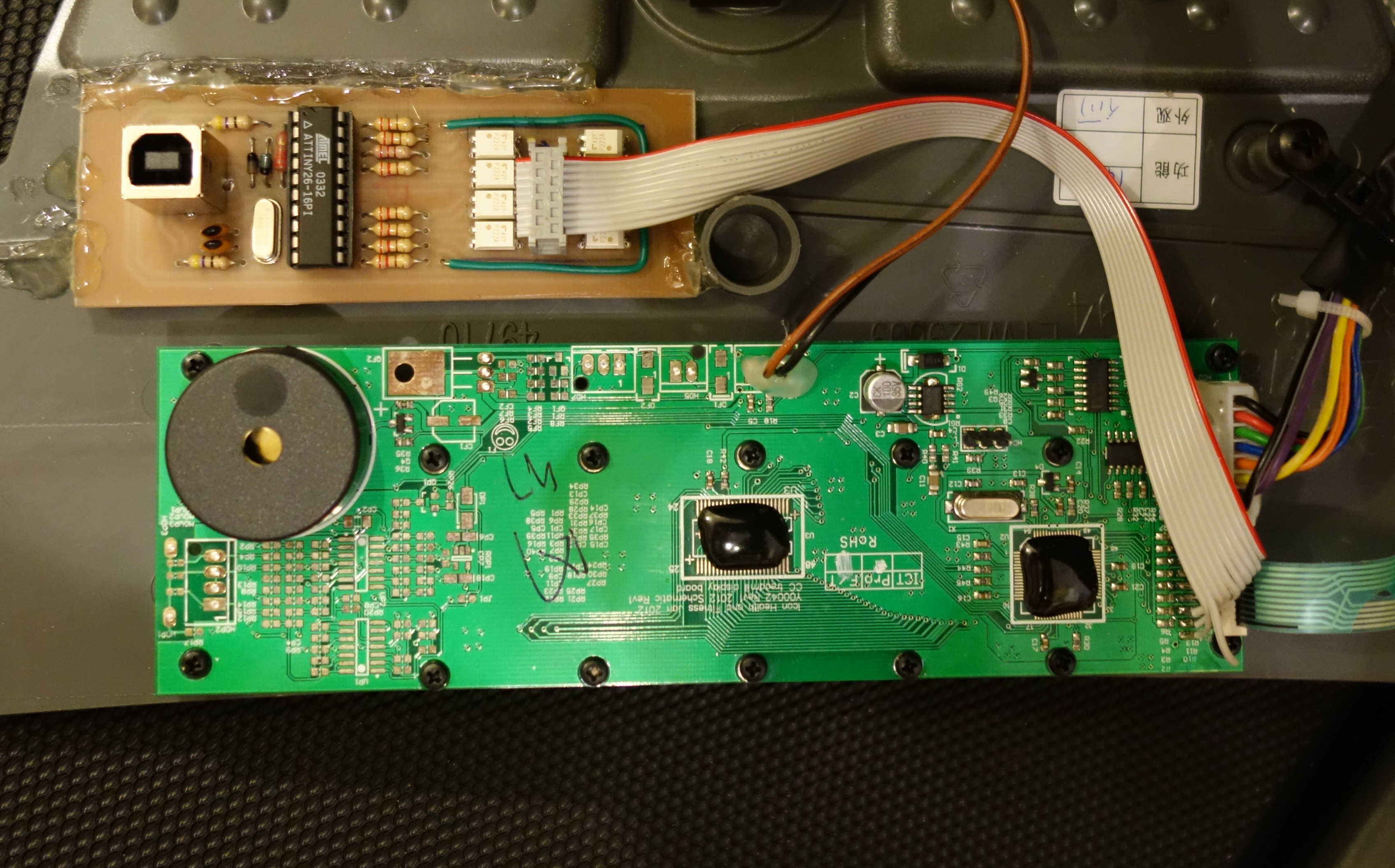
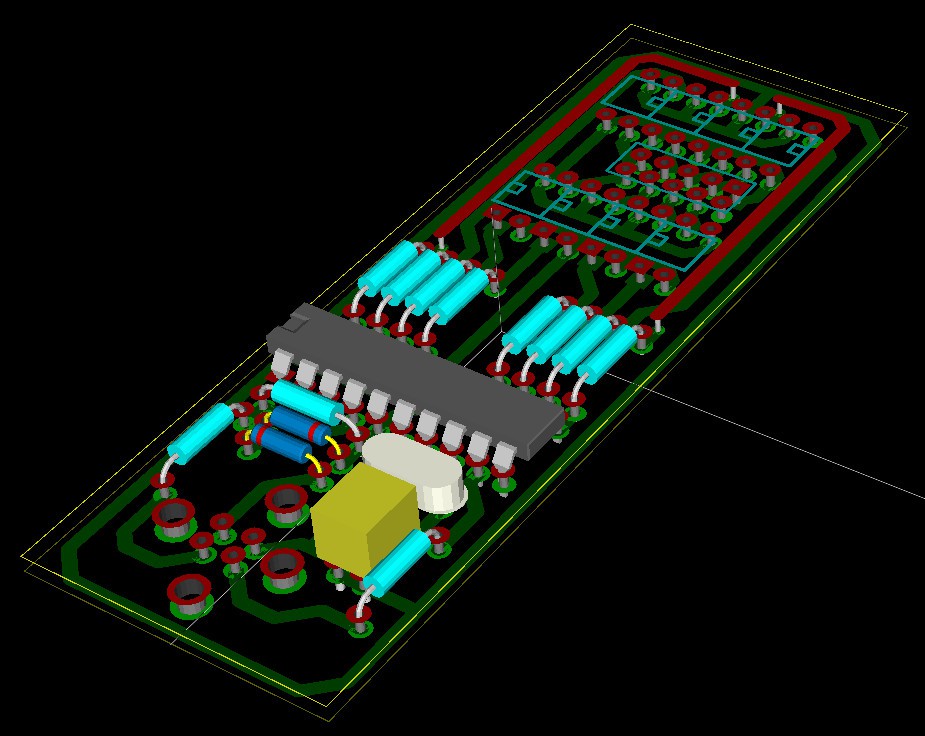
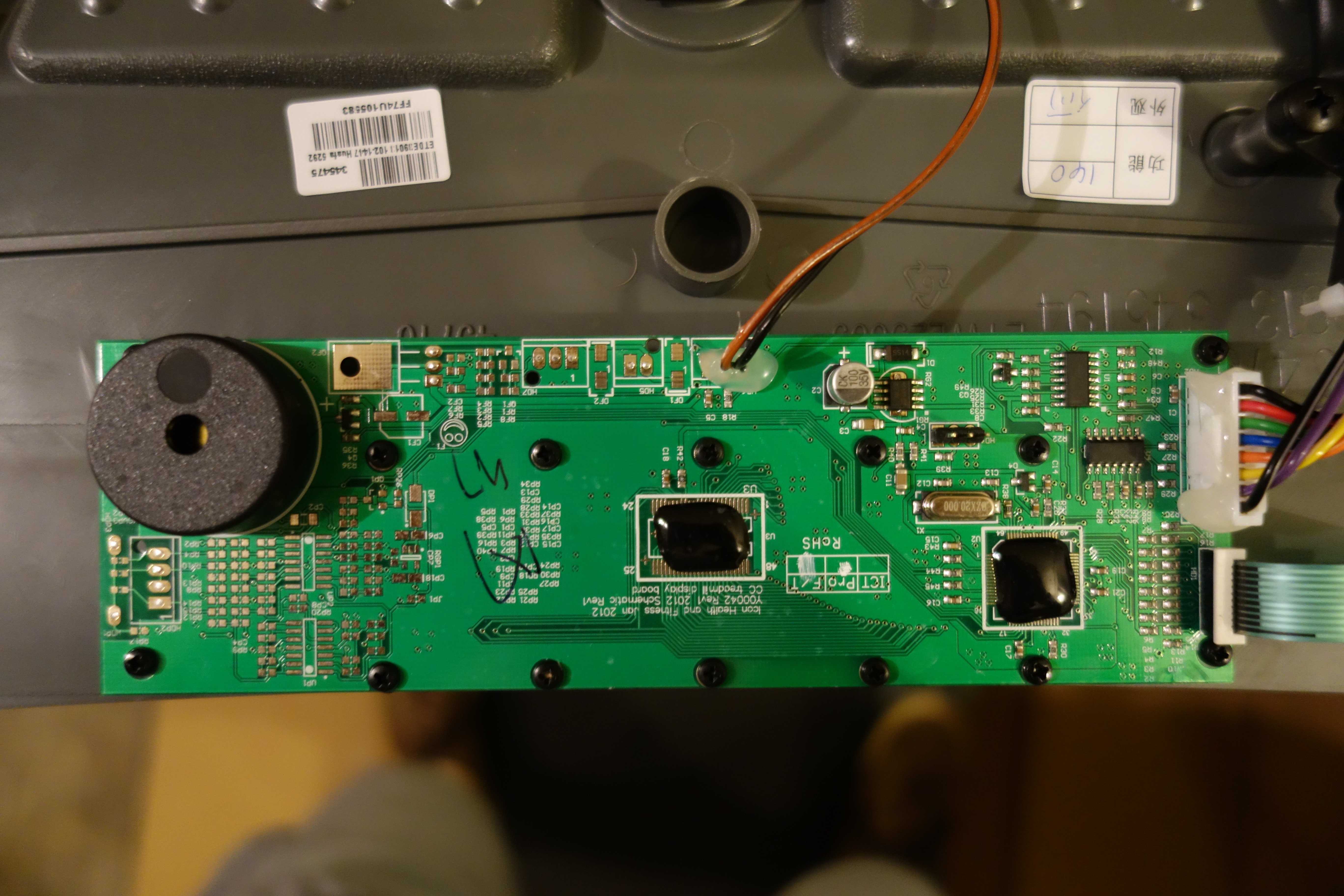
This was the easy part. Next, the question is: how to interface with the treadmill ?
Follow us on Facebook, and via our web site.


 RasmusB
 Julian Calaby
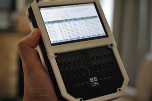
 Richard
 benjaminaigner