 Enrique
TO DO list:
Make a video explaining the initial ideas
Make a video explaining the color display
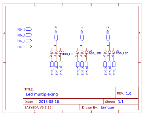
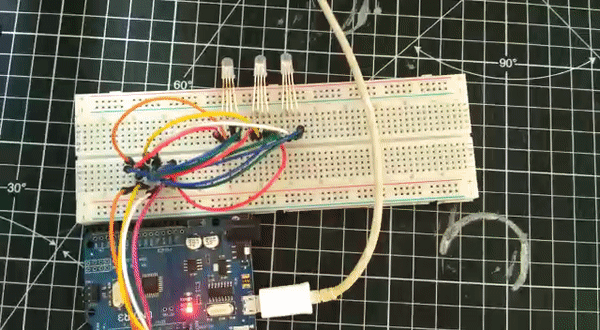
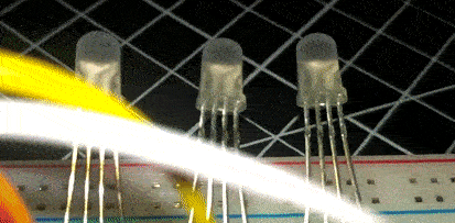
Multiplexing / charlieplexing RGB leds with few pins possible
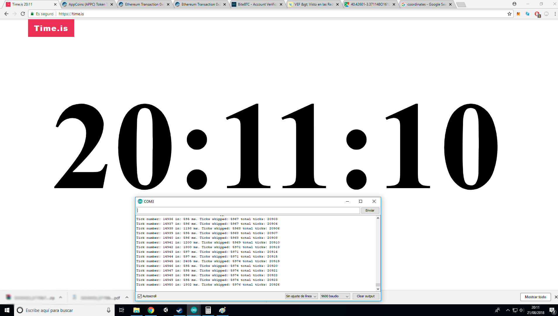
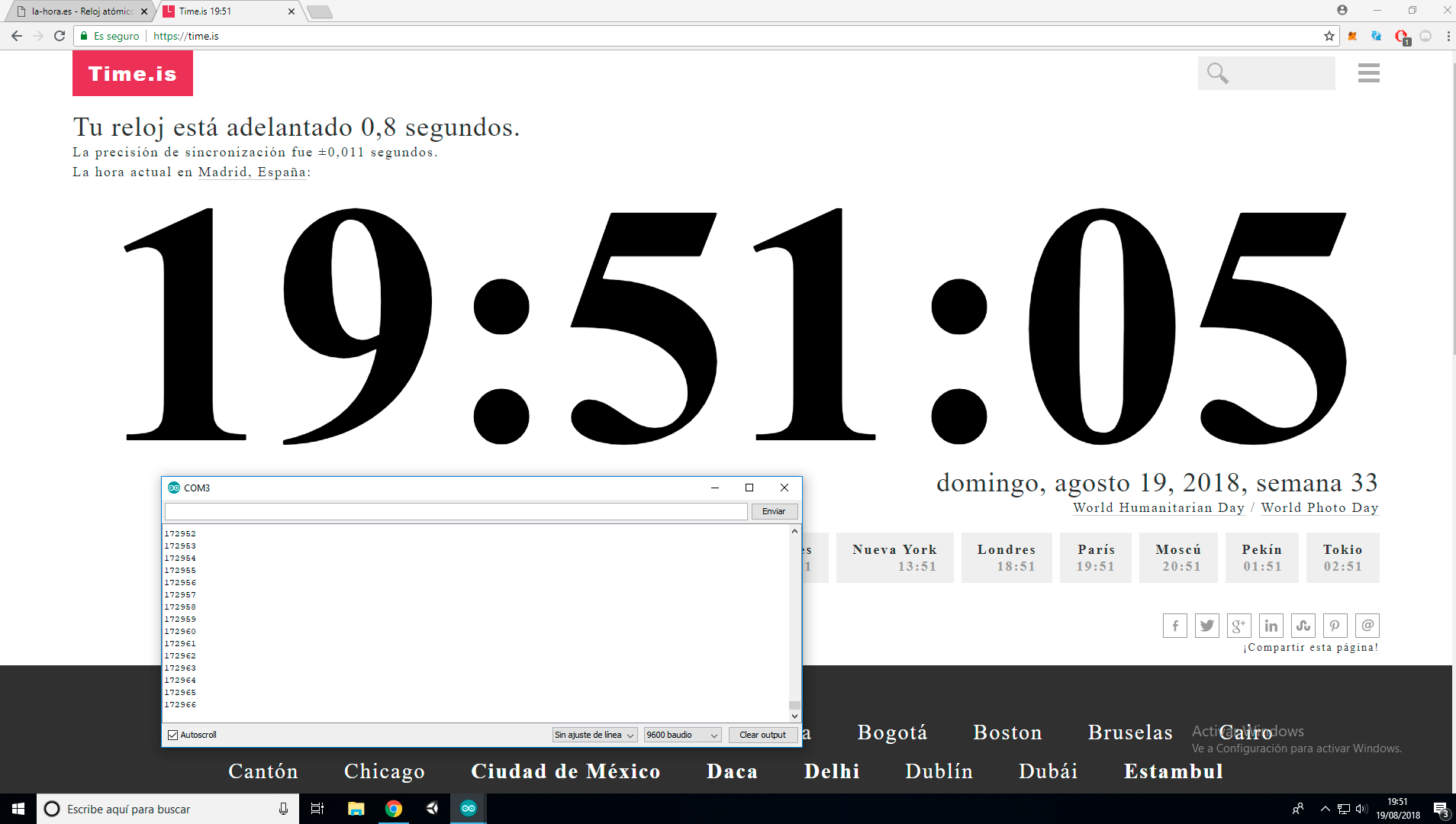
Check for attiny45 watchdog accuracy
Check for TLP5110 timer accuracy
Design a prototype pcb
Test capacitive buttons
Design a power management unit
Design a charging port
Design a final pcb
Etching a flex pcb
Make an SLA benchmark for test the width limits
Test SLA diffusers
Details:
So the current version, with 4 CPH3225A can hold 180mJ of energy (assuming a 100% of efficency) can power the attiny45 sleep at 6.4uA (21.12uW) for 8522 seconds, or 2 hours and a half. This setup is only for testing pourposes, I have to find better super caps, and more energy efficient uC with attached rtc if is possible. It also have a precision of 0.43% more or less, which is a delay of 6 minutes a day
Brief history:
So my first attemp to make this was a couple years ago, I tried to mix some ws2812b, a pair of coin cell rechargable batteries (4.8mm of diametter) and an attiny10, but it got harder than I thought. The batteries weren't enable to provide enough power for the leds, so I had to switch to supercaps, the attiny10 didn't had enough memory for control the ws2812b and didn't had enough pins for driving normal rgb leds, so I had to switch to a attiny45, with more ram and more pins

 Paula
Paula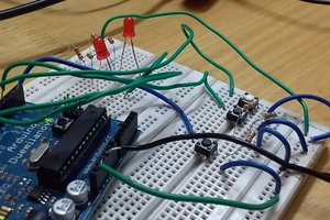
 Jayraj Desai
 Scott Clandinin
 Stefan-Xp