 Enrique
One of the most important things in this project is the display, 3 rgb leds, but 3 rgb leds means 3 * 3 colors = 9 pins. One solution is a charlieplexed arrangement, which allows me to use only 4 pins
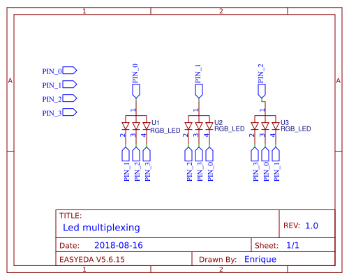
so in theory, playing with different pin digital outputs and inputs is possible to turn an specific color.
So let's code a bit:
first I need a function that turns all off:
// turn all pins off by putting them in a high impedance state
void turnOff(){
  pinMode(PIN0, INPUT);
  pinMode(PIN1, INPUT);
  pinMode(PIN2, INPUT);
  pinMode(PIN3, INPUT);
}
The pinMode function allows to set a pin as a 0/1 (OUTPUT) or as a high impedance state (INPUT). Setting it as an input is like turning that pin off, no digital data coming out that pin.
So now I need a function for control which color of which led turn on, so there is:
// turns on one led one color at time, 3 available leds and 3 available colors (0 = BLACK, 1 = RED, 2 = GREEN, 3 = BLUE)
void turnOn(byte led, byte color){

  //turn all pins off
  turnOff();

  switch(led){
    case 0:
      // set the common cathode on
      pinMode(PIN0, OUTPUT);
      digitalWrite(PIN0, HIGH);

      // set the mapped pin to off
      if(color == 1){
        pinMode(PIN1, OUTPUT);
        digitalWrite(PIN1, LOW);
      }

      if(color == 2){
        pinMode(PIN2, OUTPUT);
        digitalWrite(PIN2, LOW);
      }

      if(color == 3){
        pinMode(PIN3, OUTPUT);
        digitalWrite(PIN3, LOW);
      }
      break;

    case 1:
      // set the common cathode on
      pinMode(PIN1, OUTPUT);
      digitalWrite(PIN1, HIGH);

      // set the mapped pin to off
      if(color == 1){
        pinMode(PIN2, OUTPUT);
        digitalWrite(PIN2, LOW);
      }

      if(color == 2){
        pinMode(PIN3, OUTPUT);
        digitalWrite(PIN3, LOW);
      }

      if(color == 3){
        pinMode(PIN0, OUTPUT);
        digitalWrite(PIN0, LOW);
      }
      break;

    case 2:
      // set the common cathode on
      pinMode(PIN2, OUTPUT);
      digitalWrite(PIN2, HIGH);

      // set the mapped pin to off
      if(color == 1){
        pinMode(PIN3, OUTPUT);
        digitalWrite(PIN3, LOW);
      }

      if(color == 2){
        pinMode(PIN0, OUTPUT);
        digitalWrite(PIN0, LOW);
      }

      if(color == 3){
        pinMode(PIN1, OUTPUT);
        digitalWrite(PIN1, LOW);
      }
      break;
  }
}
What this function does is to turn on one led one color (R/G/B) at time turning off the rest, so lets test it:
Now we want to represent decimal numbers as an octal color coded ones:
void drawNumber(int number, int milliseconds){

  float startedMilliseconds = millis();

  // run the while for the time set
  while(startedMilliseconds + milliseconds > millis()){

    // loop for each led
    for(int i = 0; i < 3; i++){

      // n is the octal number corresponding to ith digit, this is the main decimal to octal conversion
      int n = (number/round(pow(8, i)))%8;

      // loop for each binary digit on n
      for(int j = 0; j < 3; j++){
        // we get the jth binary digit and check if is a 0 or a 1, turning on or off the corresponding color, for example 5 = 101 which would turn red and blue = magenta
        if((n/round(pow(2, j)))%2 == 1){
          turnOn(i, j+1);
        }else{
          turnOn(i, 0);
        }

      }
    }
  }
  turnOff();
}
We run the function in a while loop for the time that we want the leds turned on, after that, we convert the digital number ("number" variable) into 3 octal digits, each one corresponding to one led, this digit is called "n". Now we get the n and we decompose it into binary digits in the second loop. How the n is a number between 0-7, we only need 3 binary digits. Each binary digit is represents a RGB color on a led so for example the 5 = 101 would turn on the red led, would turn off the green led and turn on the blue, so we would get magenta. Let's see it in action:
And that's, sorry for the terrible quality, I had to compress the gif
So now, we can get any number between 0 - 511 and show it with 3 RGB leds and 4 microcontroller pins!
Stay tuned for the next log
Discussions
Become a Hackaday.io Member
Create an account to leave a comment. Already have an account? Log In.