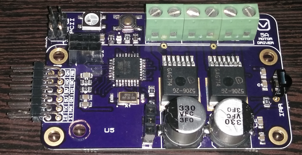
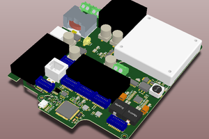
Here comes the finished board.
- Works completely as expected. The RGB LED on top is used for error / or any other indication. The LED on bottom of the board serves as a Voltage indicator (Battery Voltage circuit built-in). The color gradually fades between Green to Red according to change in input voltage.
- U5 space is used for adding a plug-in step down voltage module with 7805 regulator pinouts.
- Controller intelligently selects the input module. The input can be either RC Remote, I2C, Bluetooth, or Infrared.
- Reset Circuitry to reset the board once the input control method is changed.
- The board is fully Arduino Compatible
- Two I2C interfaces. One to connect the controller and other to connect multiple modules in Series
- A bottom connector on the board can be used to mount the boards in series to connect multiple motors
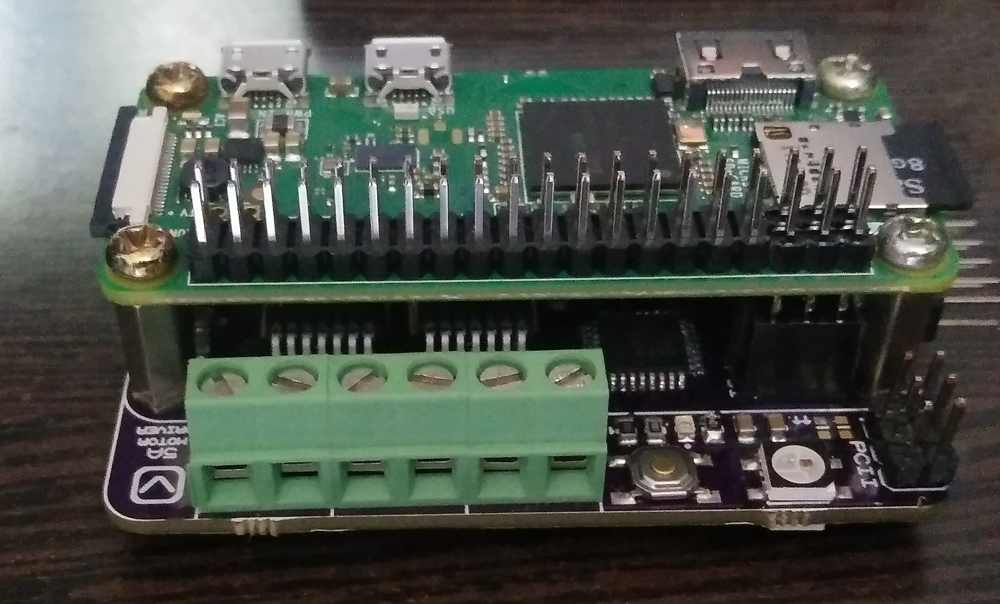
A Raspberry Pi Zero W mounted over the controller board. The pin-outs are compatible with other Raspberry Pi Boards too.
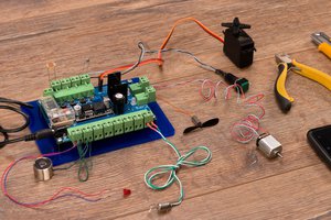
Finally, here is a video showcase of board running two DC gear motors in I2C mode. The voltage indicator changes color based on the change in input (battery) voltage.
 Oktopod Studio
 Hosein Movahedian Attar
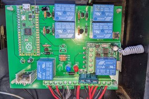
 Ian Dunn