 Rami
RamiLinear generator in this study is used as a power take off mechanism. using Ocean waves as source of energy, linear generators are used as direct electrical drive system that can extract power from wave directly into electrical form without a mechanical intervention between them. This will save a lot of maintenance and repatriation for its lack of many components like gearbox and others. Figure 3.1 shows a simple diagram of this three phase permanent magnet linear generator:
Figure 3.1: Modeling of three phase permanent magnet
The wave exciting force and the hydro mechanical force acting upon the floating structure (i.e. translator) will lead the translator to move inside the stator. This movement of magnet will lead to a change of the magnetic flux within the stator and by faradays law this will induce a current in the winding coils by a phenomena called electromagnetic induction. This generator is consisted of highly conducting cables, structure steel, light weight floating structure, and permanent magnet embedded with iron and coal. The magnet material used will be described in section 4.3. However, how the stator core is fixed? Many studies show the stator should be moored to the seabed and this need strong ropes that can last for a long time and bear this stator under all weather and environmental changes. Linear generator will have a pretty output of voltage and current as long as the magnetic flux is changing within the stator. The relative motion between the stator and the translator becomes very crucial in a three phase generator. To achieve this, a number of springs should be added in addition to the hinges between the part of the floating structure and the new design is becoming as shown in the following figure 3.2:
Figure 3.2: Detailed model of linear generator
These will not prevent from using ropes to fix the system in one position. In the above design when the translator moves up the stator will moves down by the help of the sticks attached to the hinge. For more clarity, the floating structure- attached to the stator- is stacked to an arm where rotation is allowed. This is the same between the arm and the floating structure attached to the translator.
3.2 Mechanical Modeling of the arm
As mentioned above, the arm is attached to the stator and the translator. This arm is formed of two revolute joints for rotation from its ends and one prismatic joint in the middle connecting the two links of the arm for linear displacement between them. Therefore the arm is made up of 3 joints each with a single degree of freedom of motion and up of 4 links. The arm is shown below figure 3.3:
Figure 3.3: Modeling of the arm and joints
“A” represents the floating structure attached to the stator and “B” to the translator. In this section, the relative motion of “B” to “A” and the position and the orientation is determined in terms of the joint variables. This is so called kinematic study where the motion is considered without studying the causes of motion i.e. forces and torques.
Let’s first use the Denavit-Hartenberg (DH) convention that uses four basic transformations [4]:
=
=
=
: is the angle of rotation
: is the distance of displacement
= distance along from the intersection of the and axes to .
= distance along from to the intersection of the and axes. If joint i is prismatic then is variable and denoted by .
= the angle from to measured about .
= the angle from to measured about . If joint i is revolute, is variable and denoted by .
Keeping in mind the actuating of the joint...
Read more »
 César Castillo Andrade
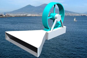
 Anteneh Gashaw
 Aron Molnar
 Michael Perrone