 Code Your Venture Free
TL;DR, You can just watch the Youtube video
Hey, this is Ben, a developer from Hong Kong. This is my first time to write an article and I just want to share one of my recent project on the internet.
Problem : Broken Gaming Experience
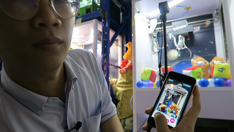
Long story short, I and Chris (my startup partner) have found a startup called Teleclaw last year. So what the hell is it? Actually, Teleclaw is a mobile application to play claw machines online remotely. So right now you can control the claw machine anytime and anywhere through a real-time streaming camera. Awesome?
But here’s the problem. When I tell my friends about this idea, they always challenge me. This app cannot completely mimic the gaming experience of a real claw machine. After all the investigations and feedbacks from our users, what we missing here, is the hand feel of controlling the joystick to play the game. That’s the most important gaming experience.
Solution : ioT joystick to play the claw machine online remotely
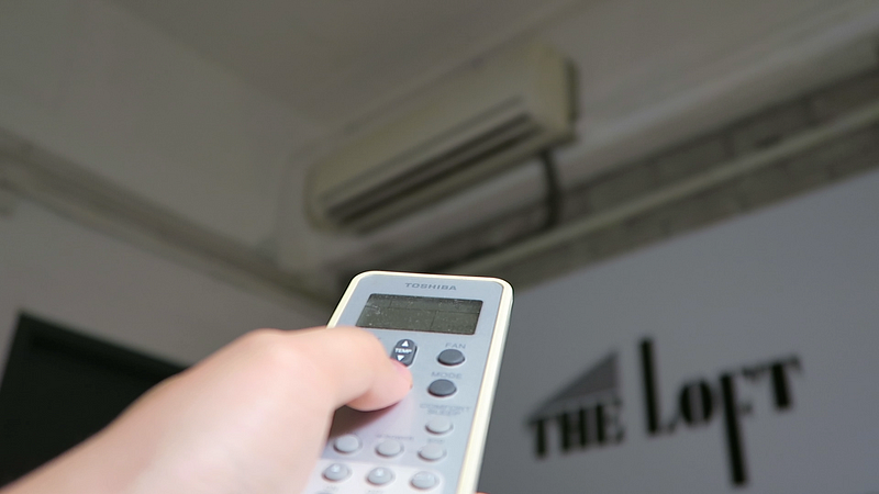
My solution is to develop a handheld control that can play claw machines directly. The purpose is to narrow down the gap between a real joystick and a virtual one. Same as the remote control for your air-con at home.
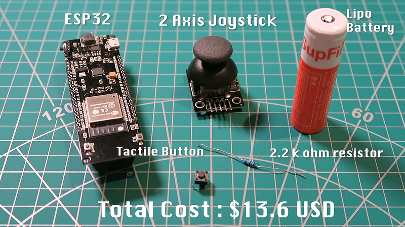
Here’s the bill of materials for this project: an ESP32 module, a 2-axis joystick, a lipo battery, a 2.2 KOhms resistor. Last but not least, a 6mm tactile button switch.
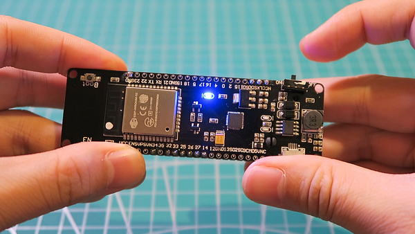
The reason that I choose the ESP32 module from “WEMOS” is simple. It comes with a battery solution by default that saves you much more time in power management.
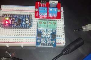
Step One : Schematic
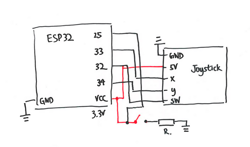
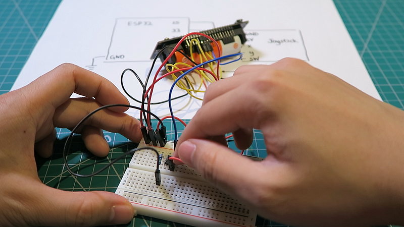
Try to draft a schematic diagram and test out the circuit on the breadboard. Testing out the circuit before soldering the components together will save you much more time in the prototyping process. Bear in mind that although the label on the joystick is 5v, 3.3v is still an acceptable working voltage according to my experiment. That’s why no boost up board is required.
Step Two : Coding
Write and upload the code to the ESP32 module. To keep it simple, I would like to use the Arduino IDE to program the logic.
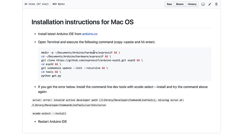
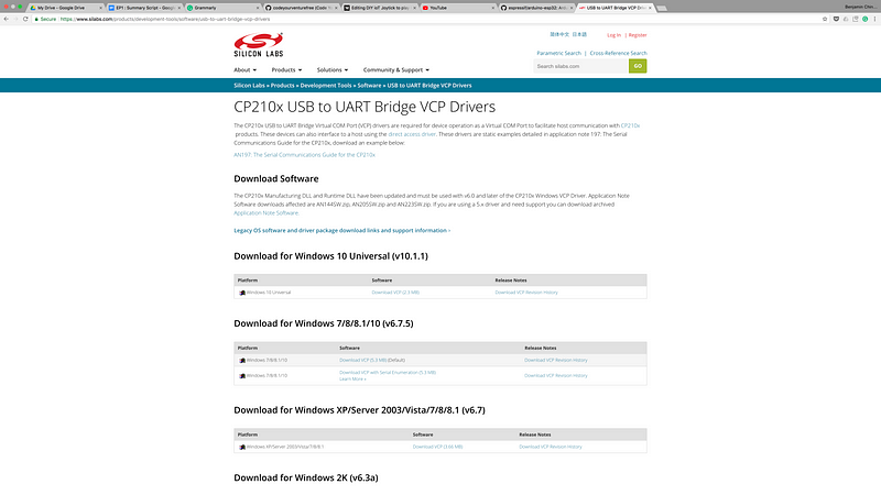
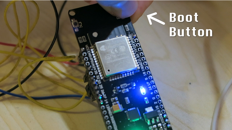
However, it’s a little bit tricky to setup the development environment. So please follow the documentation on GitHub and download the USB driver from Silicon Labs. For some models of the ESP chips, long pressing the boot button when you upload the code.
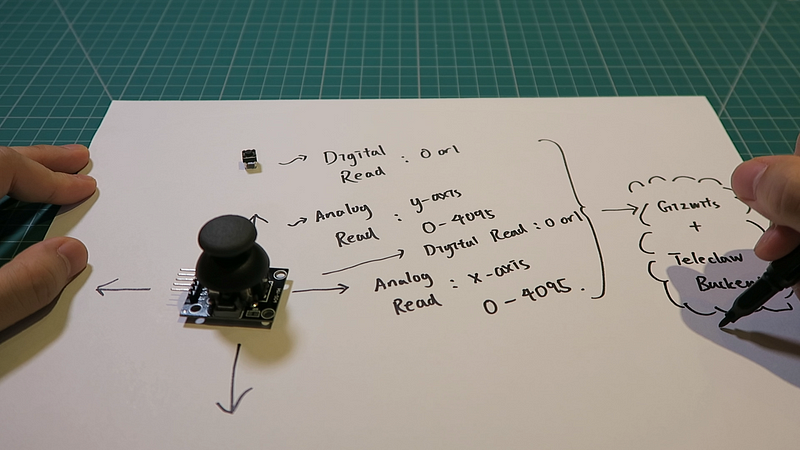
After setting up the environment, let’s go through the business logic of our code base. Under this schematic, the microcontroller will have 4 different inputs: the digital reading from the joystick switch and button switch, the analog reading from x-axis and y-axis of the joystick. Base on these four inputs, we can program the microcontroller to trigger different HTTP request. For instance, the analog readings from x-axis and y-axis will be used as a command to control the claw. The HTTP requests will send to our backend server via the IoT service provider in China.
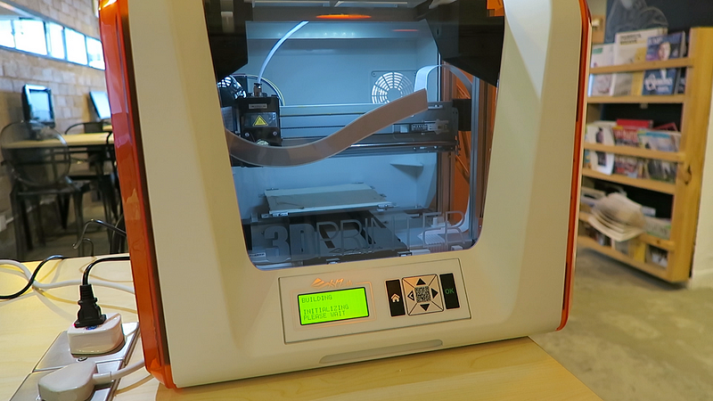
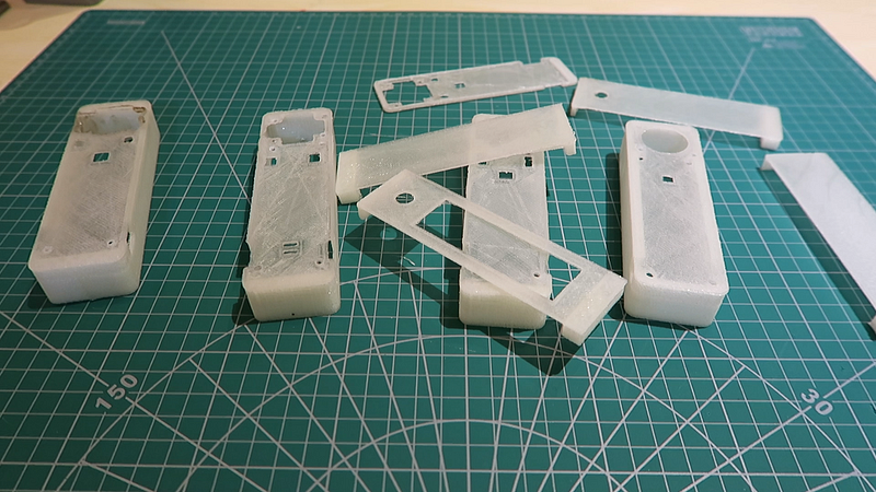
Finally : 3D Printed Case
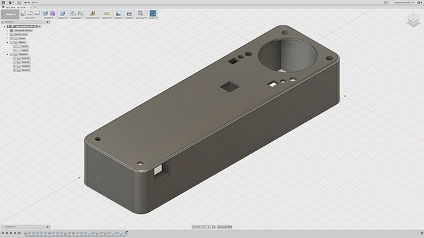
We definitely need a case to house our electronic components. By precise measurement of the components, I use fusion 360 to design a basic model and print it out with my old 3d printer.
After several failures and prototyping, finally, there is a 3d model that I really satisfy. The resolution of the printing is obviously not the best, but it is still good to go as a prototype.
So, everything is ready now and let’s put them all together. After couple hours of hard working, Wa la here’s the first prototype and let’s play the claw machine.
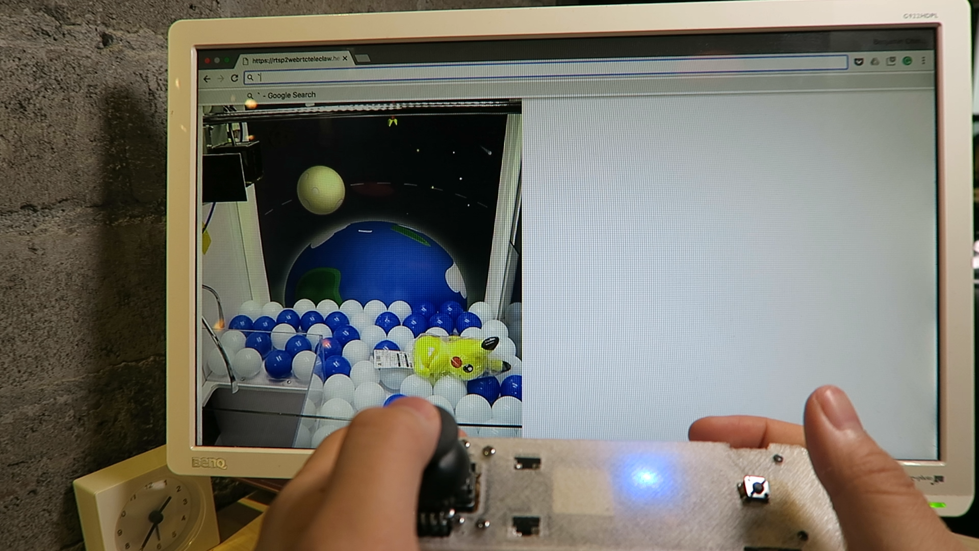
Although it is a little bit laggy, this prototype is still a great attempt to be a proof of concept.
By the way, If you are interested in this project, don’t worry, all the files and source code are on Github.
https://github.com/codeyourventurefree/claw_machine_joystick
Conclusion
There are definitely lots of improvements in the future. For example, I would like to...
Read more »
 Pavel Semenov
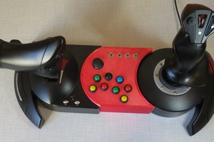
 Welsh Mullet
 Varlen