 matt venn
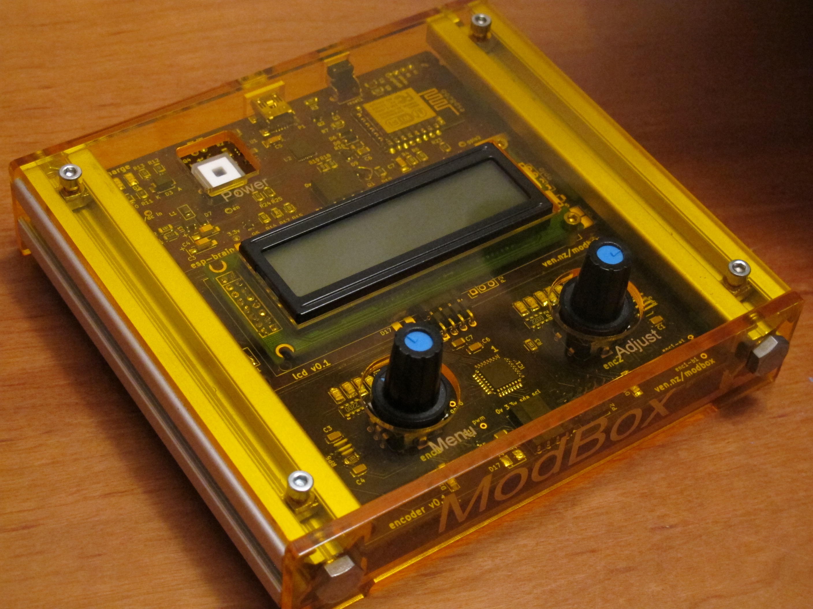
What started of as a simple music controller for my home hifi turned into a modular controller and display.
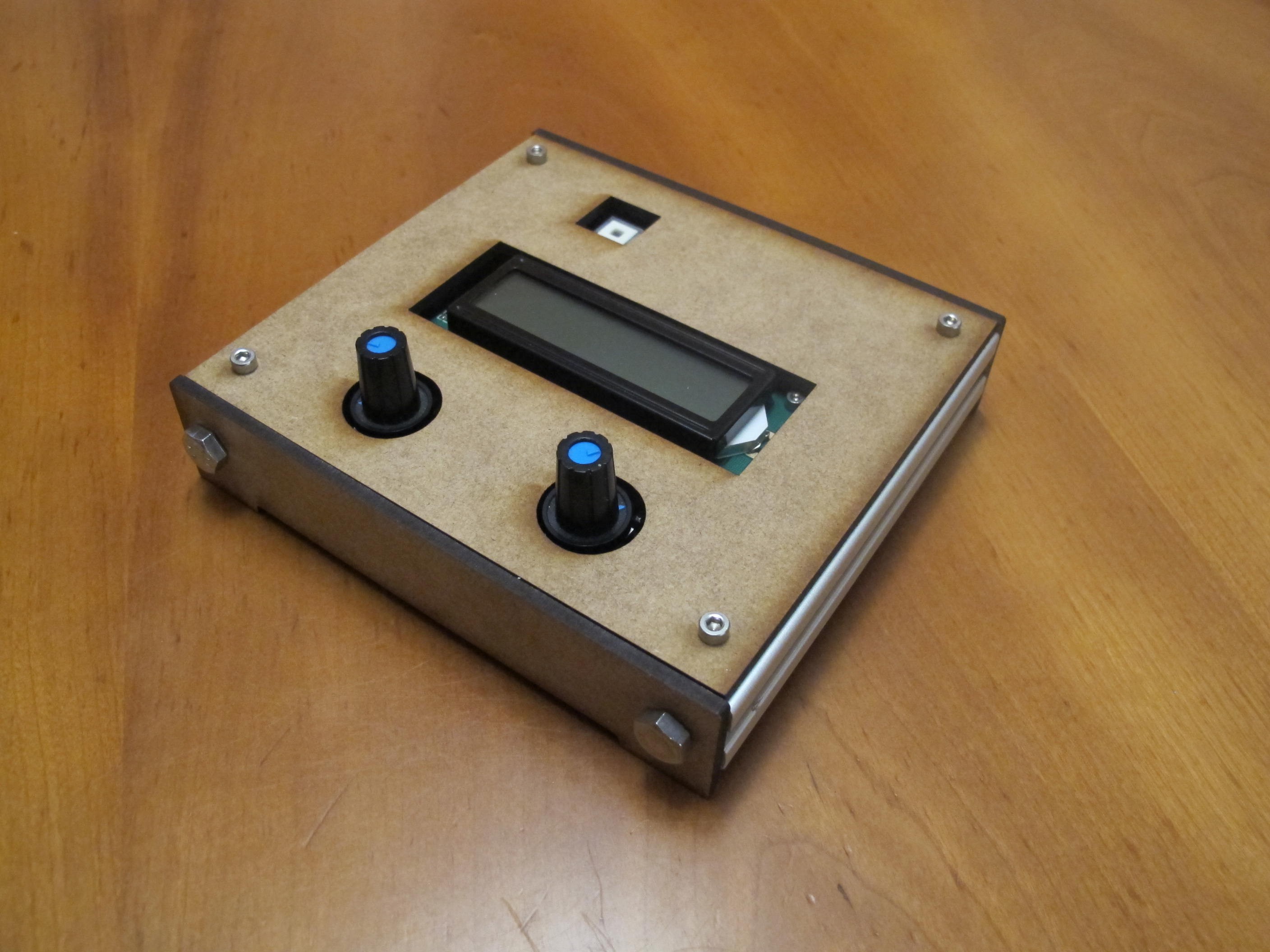
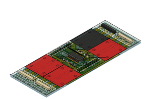
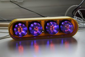
I've built 3 modules so far, a "brain" based on the esp8266, USB serial and a LIPO battery charger. This connects via a simple powered I2C bus to other modules. So far I only have an encoder module (2 encoders + led bars) and an LCD module. A module with 8 buttons is planned.
I'm experimenting with a very simple firmware on the esp and module boards - when it starts up it connects via MQTT to the server which registers the modules. The interface itself is run as python code on the server rather than in the modbox hardware. This makes it very easy to update and perform more complicated functions (like fetching currently playing track from fip's twitter stream).
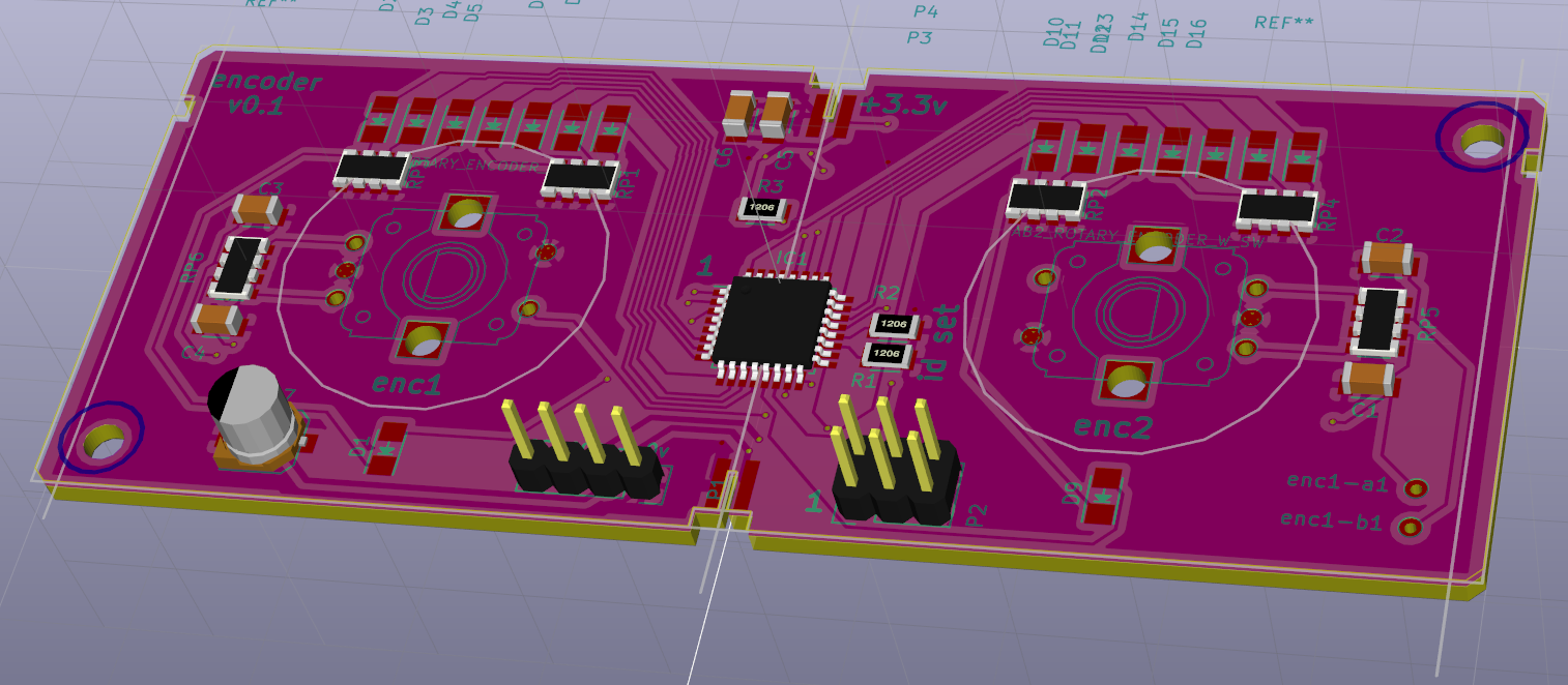
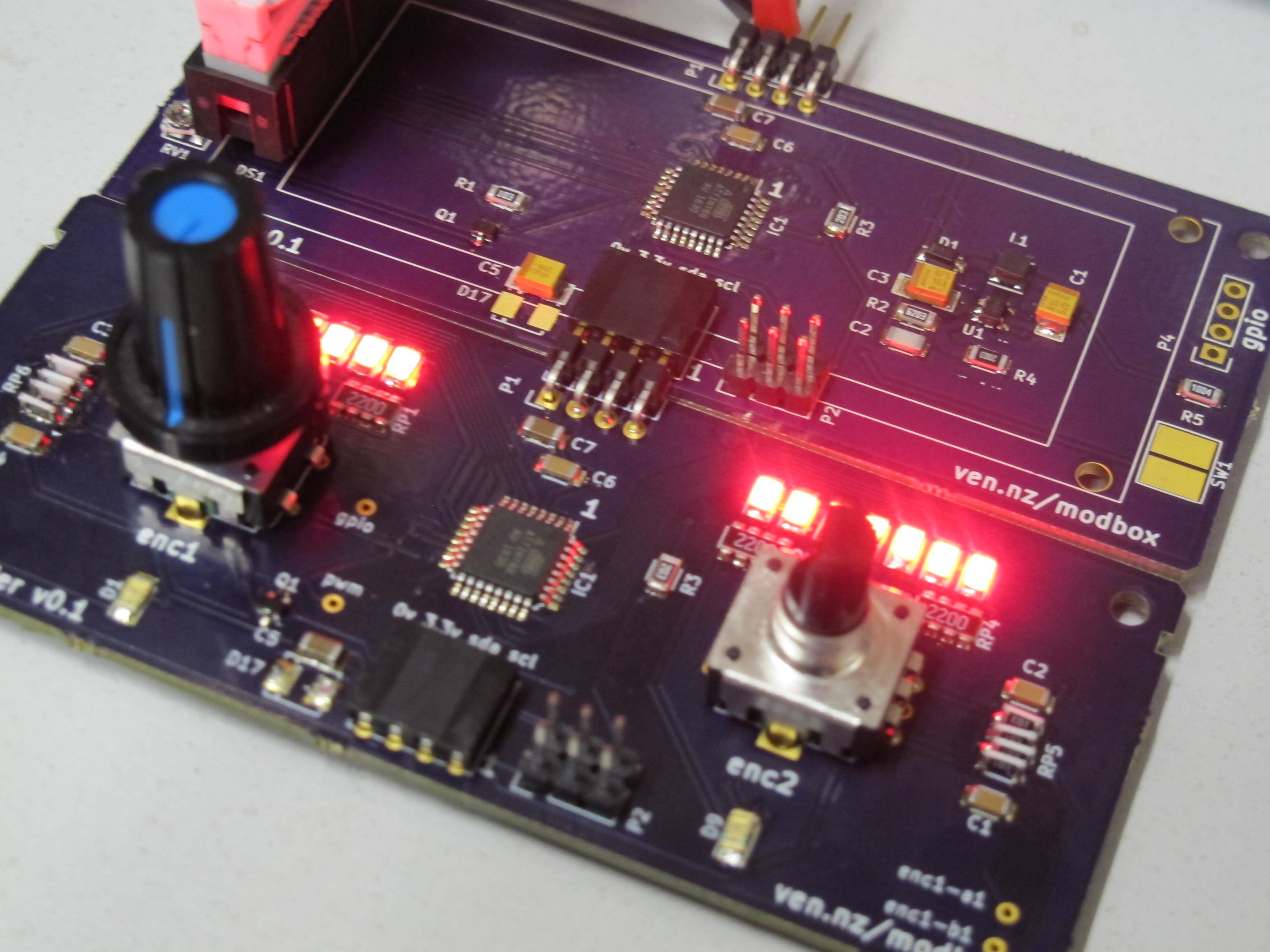 knobs & lcd PCBs arrived from OSHPark a few weeks ago - today we got round to building them up and writing some test firmware to flash the lights.
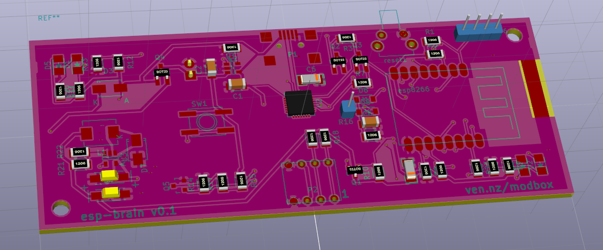
 Marek
Marek
 Involute
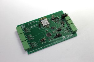
 davedarko