 Christoph Tack
Over the course of the project, development in China hasn't stopped. It's currently possible to order 4-in-1 modules with the MAX7219 on AliExpress for only €3.78.
If you only want a single piece, you could saw the module to pieces, or buy a single module for €1.09 from AliExpress.
If these modules had been available when I needed them, I probably wouldn't have taken the effort to design my own modules.
 Erik Bosman
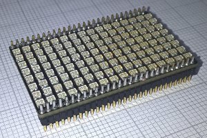
 Alex
Alex
 hesam.moshiri