 Just4Fun
The
Atmega8 is flashed with an Arduino bootloader, and is clocked with
the internal oscillator at 8MHz. Because the Atmega8 doesn't contain
a sufficient number of PWMs, a software PWM is used to drive two RGB
leds (it requires six PWM channels). A photo resistor is used to
measure the ambient light. Pressing a button until a beep is
generated, the current light level is stored. If the ambient light
goes under this level the skull starts to snore with a very annoying
noise, until the ambient light returns higher the stored level. In
this state 9 different “light effects” are displayed every 20
seconds with the two RGB leds.
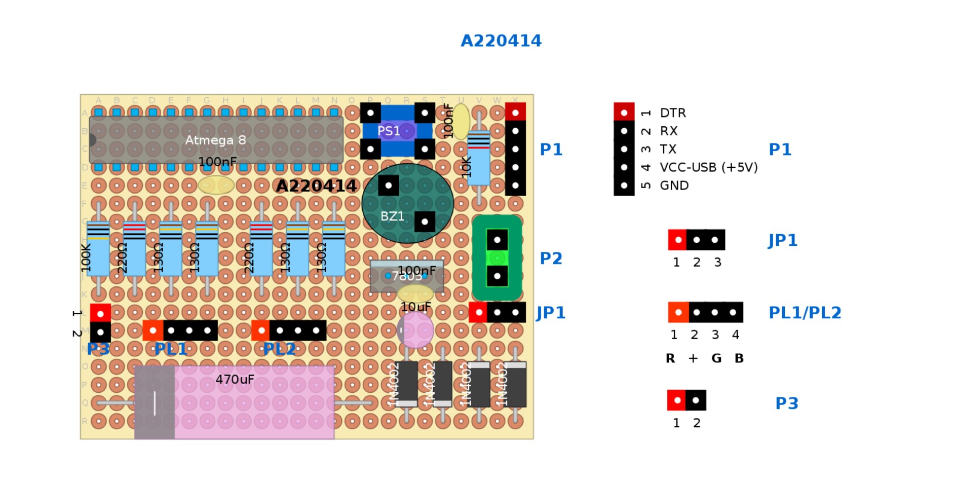
Here
the perfboard assembly layout made with an open source program: DIY Layout Creator:
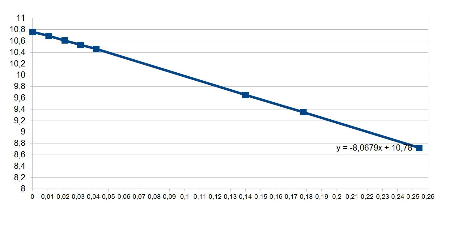
To
power this thing I used a plug transformer salvaged from a broken
multifunction phone. Because I didn't want to heat the linear
regulator too much, to make things more accurate I did some
measurements at different currents to find the transformer
“equivalent source resistance”, and with a simple interpolation I
found it about 8 Ohm (X = A, Y = V):
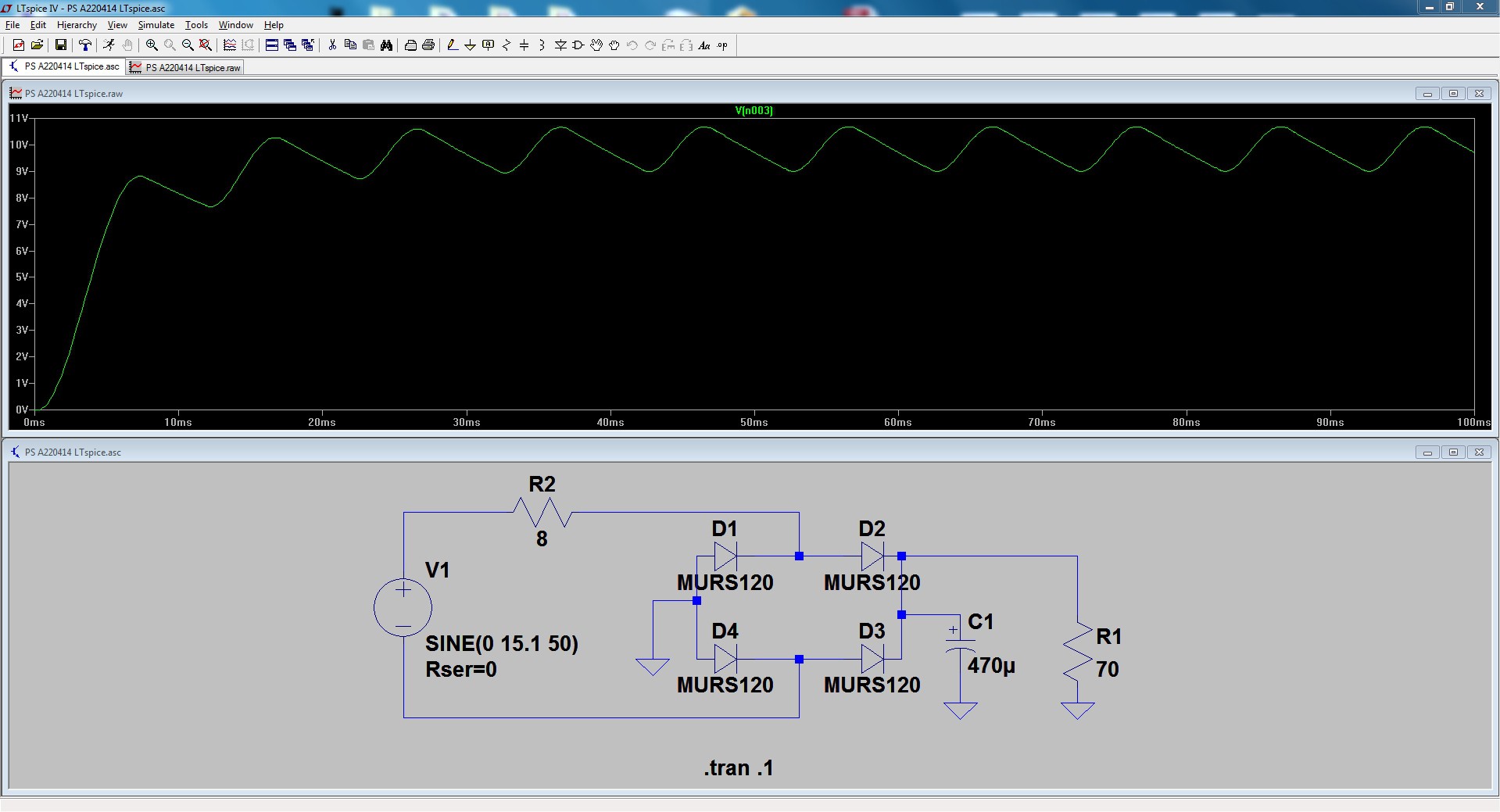
And here is a simple LTSpice model of the power supply (before the regulator). The 70 Ohm resistor simulates the load (worst condition):
 The
schematic, the perfboard assembly guide, and the sketch with the
used library are in the Files section (I did the software very
quickly, so it is a little “rude”... anyway it works as
expected).
The
schematic, the perfboard assembly guide, and the sketch with the
used library are in the Files section (I did the software very
quickly, so it is a little “rude”... anyway it works as
expected).
The schematic was hand drawn with a tablet.
 ronald
 w_k_fay
 sky-guided
 trax
trax