 Igor Brkic
ESP32 is really awesome little computer. Two CPU cores, high speed, a bunch of peripherals, wireless networking, low price. It even has a built in DAC. It's only 8-bit, but hey! It's there! No more lousy PWM filtering to get some sound from MCU.
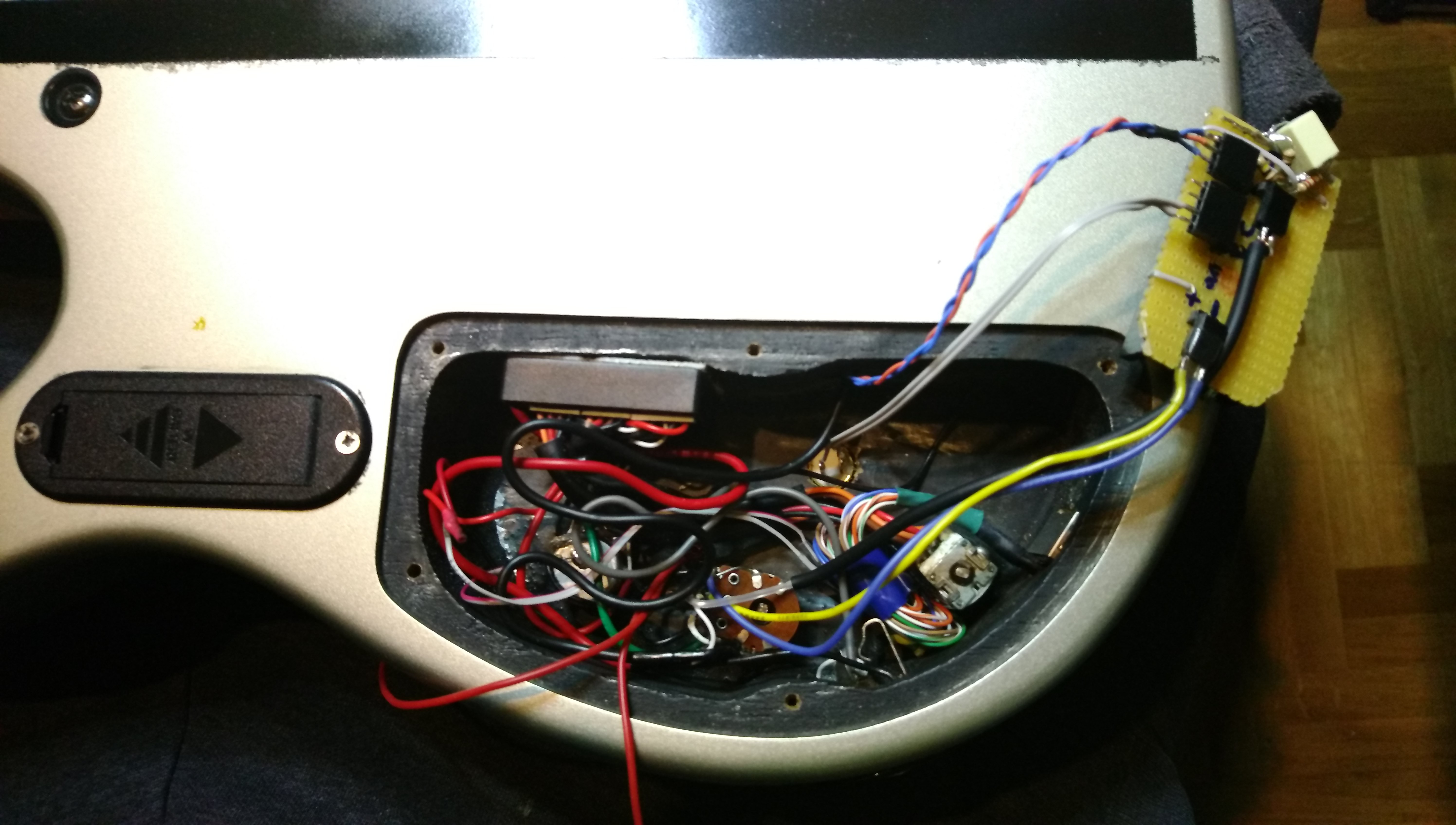
So, an idea came to me... What would it be like to build synth based on that CPU. I was really surprised not to find existing synth designs for it so I decided to make my own. Even better - why not build it inside a bass guitar and have cool synth sounds to mix them with direct bass sound. And the best part is that it doesn't even need keyboard - pitch can be extracted from the direct bass signal!
This is the wishlist for full design:
- ESP32 based (obviously)
- nice, analog style oscillators
- pitch tracking
- integrated tuner (since we already have pitch tracking)
- onboard controls to shape the sound
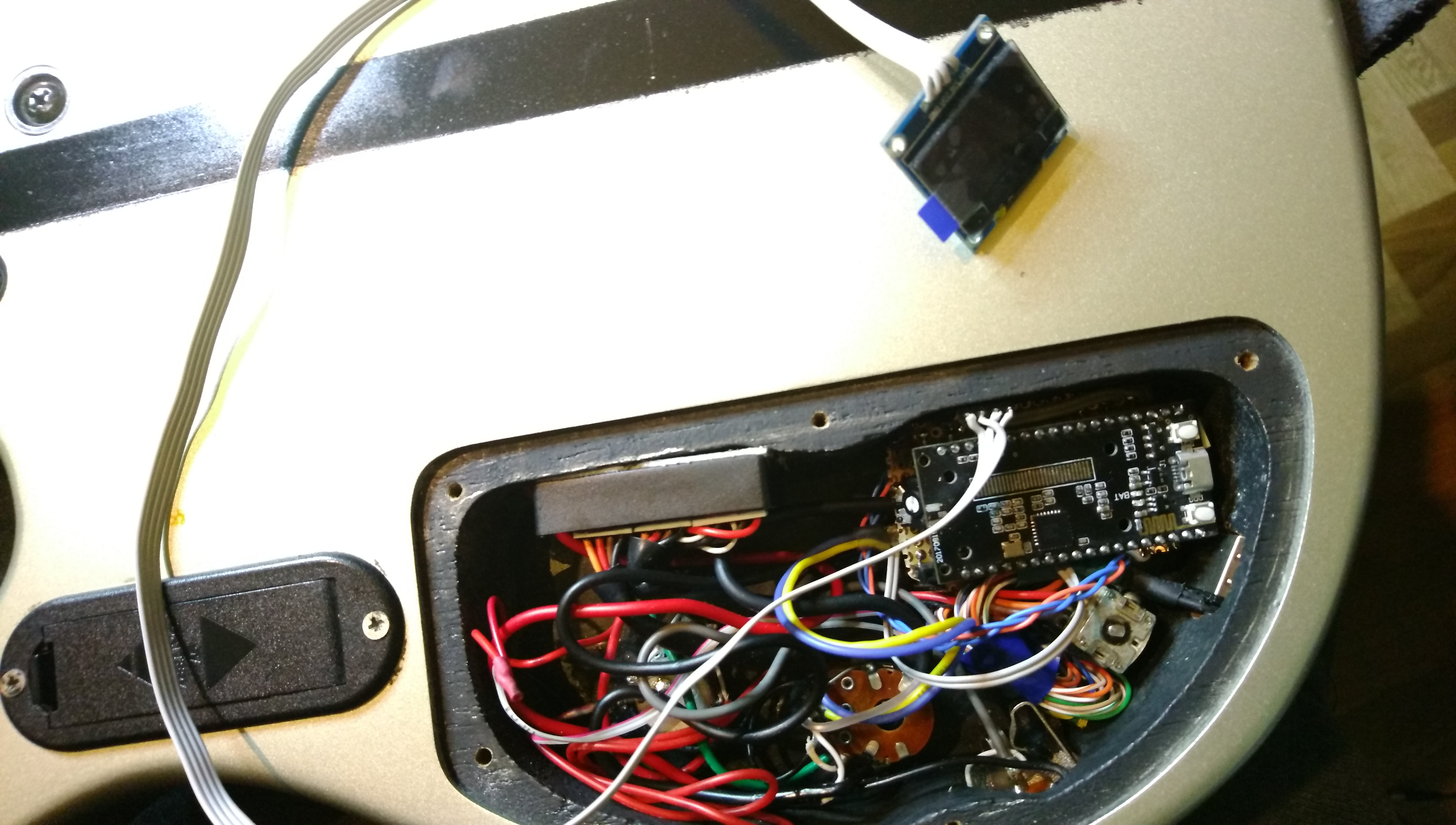
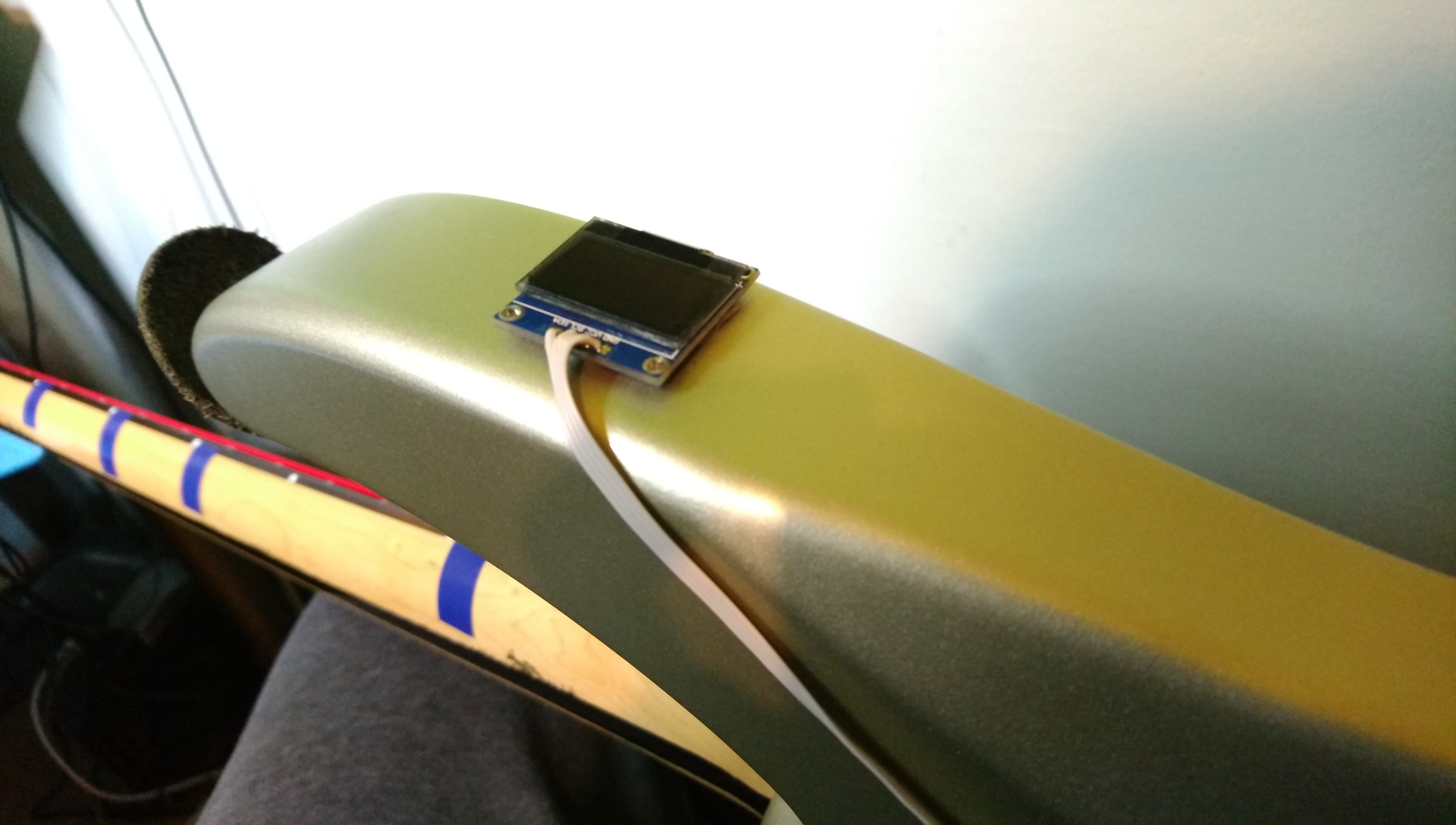
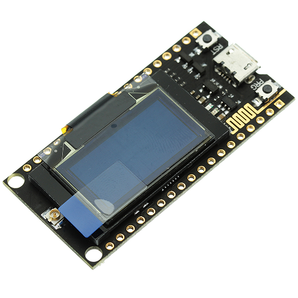
- OLED display to show the signal (some eye candy :))
- multiple patches/presets switchable during runtime
- parameter configuration done over WiFi/BLE
- try to keep the power consumption low
- (optional) MIDI support so it can be used as "desktop" module
- some better name than hgSynth
Idea is to build the first prototype using existing dev board and then do the second one on PCB with ESP32-WROOM-32U module.
Integrated DAC is only 8-bit but it will be enough for first prototype. Since ESP32 has I2S lines, external, better quality DAC, can be added easily.

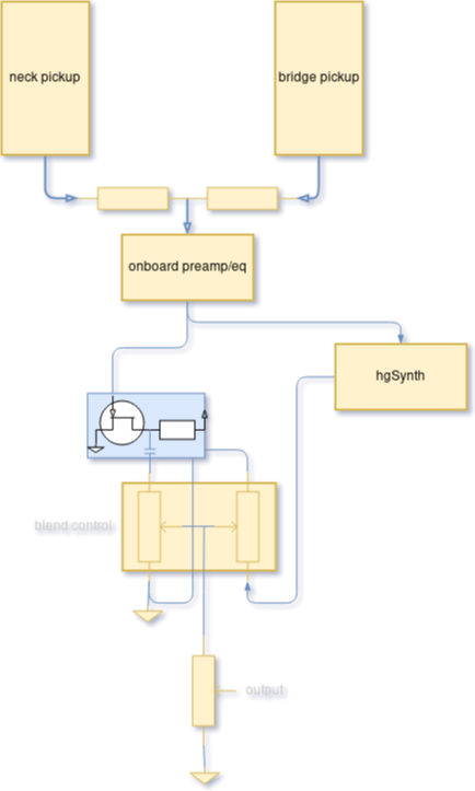
Synth is classic two-oscillator design:
- two oscillators (sine, triangle, sawtooth, square) with configurable note offset, detune
- envelope generator (same envelope is used for filter modulation)
- resonant lowpass or multimode filter
- LFO which can modulate all interesting parameters
This is initial design. I might add another LFO or envelope.

 Capt. Flatus O'Flaherty ☠

 Jesse R
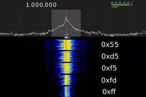
 Ted Yapo
Taking an audibly long time to determine string frequency. If you are doing FFT, try lock-in detection instead. I'll PM since its hard to attach png to a comment. Or perhaps wire frets and scan vs strings as a matrix, would give a clue what frequencys to start looking or exclude from the search.