Since PowerPACk is in essence an embedded system, these modules require a series of voltage regulators to power up all of the internal blocks. For example, logic may work with 5V or 3.3V. The CPU core needs 1.8V. The Pre Drive stage needs 12V to drive MOSFETs or 15V to drive IGBTs. The analog needs 3.3V to power up the external analog circuits Z(i.e. potentiometers, thermistors, etc.) and 2.5V as reference. So a good question is, which voltage regulators and analog blocks were chosen on these designs? None! And that is because all of the regulators required are included within the PAC52xx device!
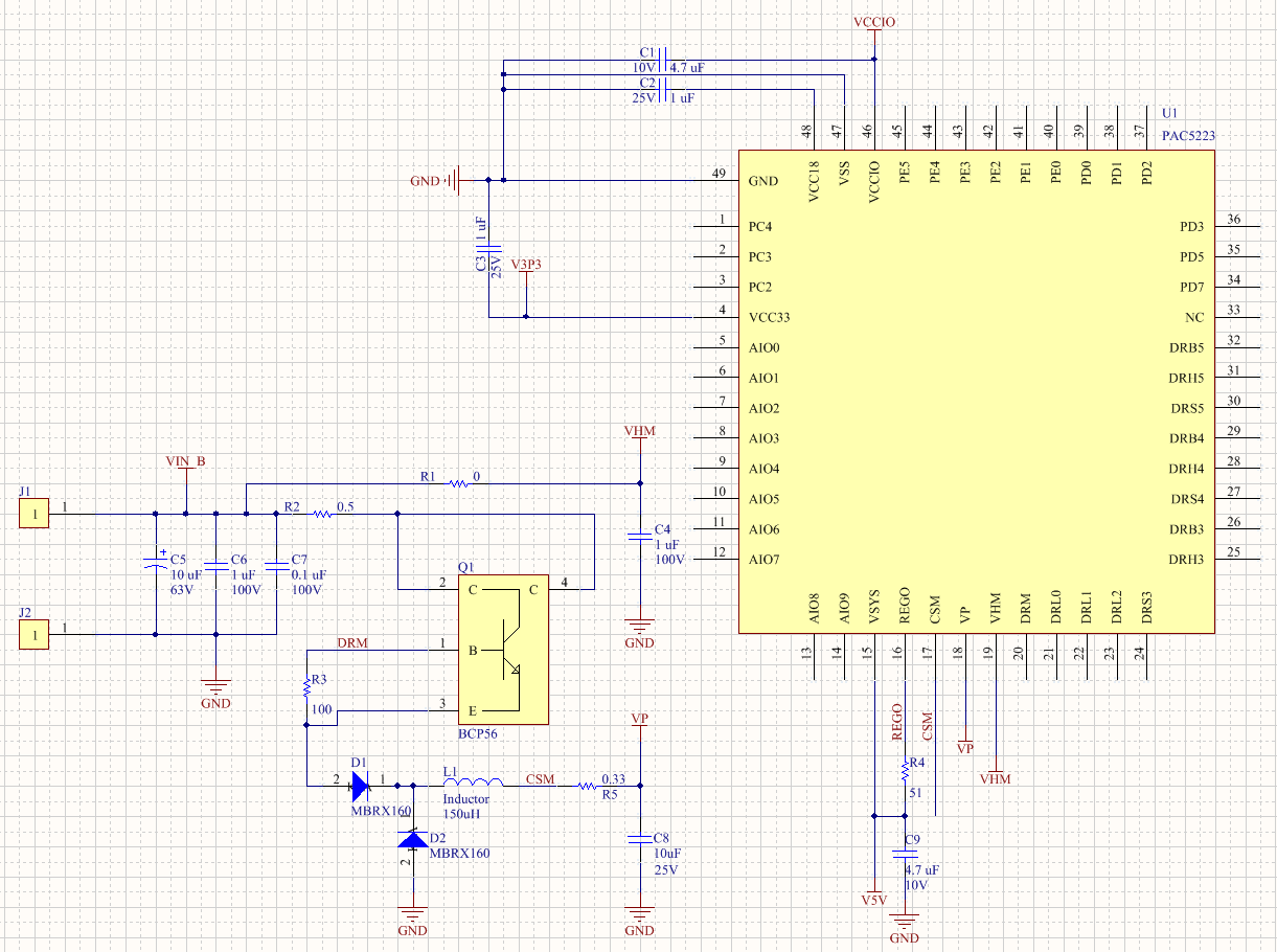
Take for example the PowerPACk23 which uses a Buck Converter (Step Down DC/DC converter) to operate with voltages as high as 70V. It generates 12V (Known as VP), which is then used to generate 5V (Known as VSYS). This 5V rail then is used to generate the MCU Core voltage of 1.8V (Known as V1P8 or VCore), the 3.3V rail for analog circuitry (known as V3P3) and the 5V or 3.3V rail for GPIO's (Known as VCCIO). Of course some components are required to form the DC/DC converter, and some decoupling caps for rail, but that is extremely typical and expected. In other words, these are components you would need anyway even if you had implemented all of these rails with external semiconductor devices such as LDO's and DC/DC switcher chips.
The following diagram shows a typical DC/DC Converter implementation around the PAC52xx family of devices.
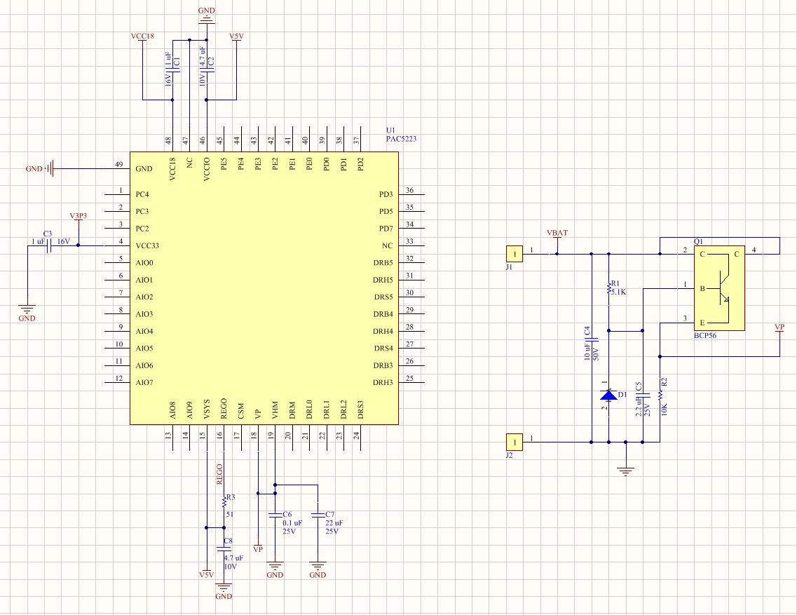
Another way in which you can power up the device is through what you can call an inductor less Buck Converter. This is in essence an LDO and you can see it being used within the Toolio PowerPACk design. In this case, we have a circuit which can operate with 18V to 20V batteries, and an Abs Max of 40V. The idea is to save a little bit on cost but mostly on space, as the inductor based Buck is rather bulky. But if your application runs on a 16V to 20V battery, what is the use of a 70V solution?
The following diagram shows a typical inductor less implementation:
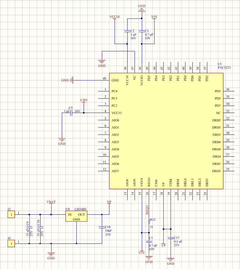
Yet you could something similar with just an LDO as shown below:
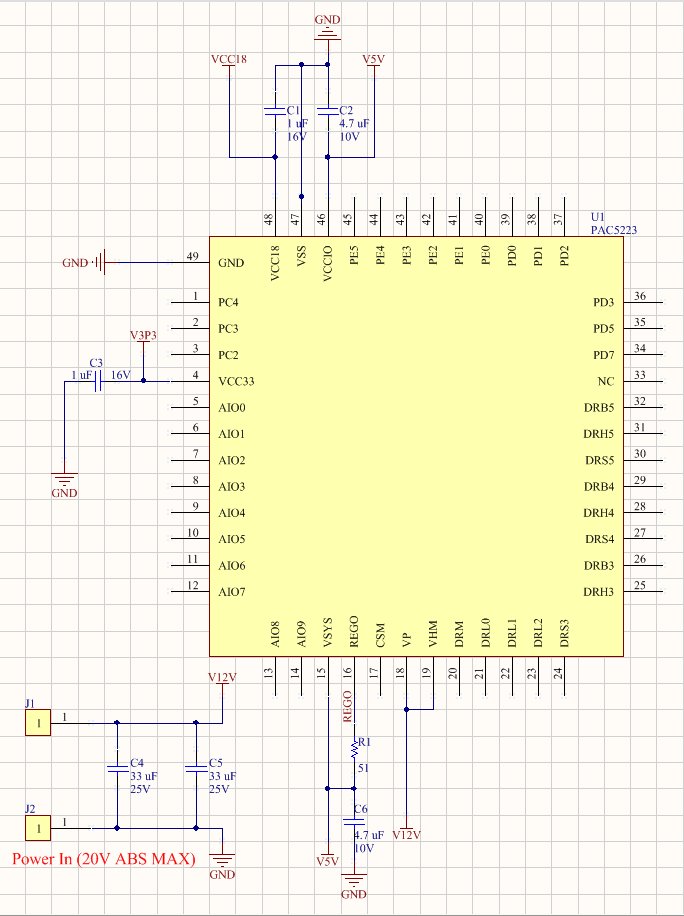
And, in the event your battery voltage and application can guarantee voltages smaller than 20V, you can skip all of the aforementioned solutions and use what we call Direct Drive, which is nothing else than the battery connected directly to VP, and having all of the internal rails being derived as detailed before. Be aware, that although this implementation has been used for small motors and low voltage applications, the 20V Abs Max is quite the limit!
The following diagram shows a Direct Drive to VP power connection:
Discussions
Become a Hackaday.io Member
Create an account to leave a comment. Already have an account? Log In.