Since the Hackaday Robotics challenge is about designing a module which can be used in a robotic application, in this video I show a way in which you can use one of the PowerPACks to drive a dual Brushed DC Motor robotic platform. Now, this may seem weird as what I have been selling the PowerPACks for is driving tri phase BLDC Motors. Yet, just because that was its main intention does not mean this is its only fashion in which they can be used. In fact, that is the beauty behind these modules! Since they are basically a microcontroller on steroids, you can use the module for pretty much anything you can think of.
What I explain on this video is that you can use one of the three Half H Bridges to drive two of the Brushed DC Motor terminals from each motor unit. Then, the other two Half H Bridges are used to drive the other side of each motor independently. What this amounts to electrically, is that both motors have a shared terminal and an independent terminal. If I apply 50% duty cycle at the shared terminals, then both motors see half of the input voltage on these terminals. I can then apply anything in between 0% and 100% on the independent terminals and what the motors will see is negative voltages and positive voltages of different magnitudes, which in turn means I can control both speed and direction on a per motor basis.
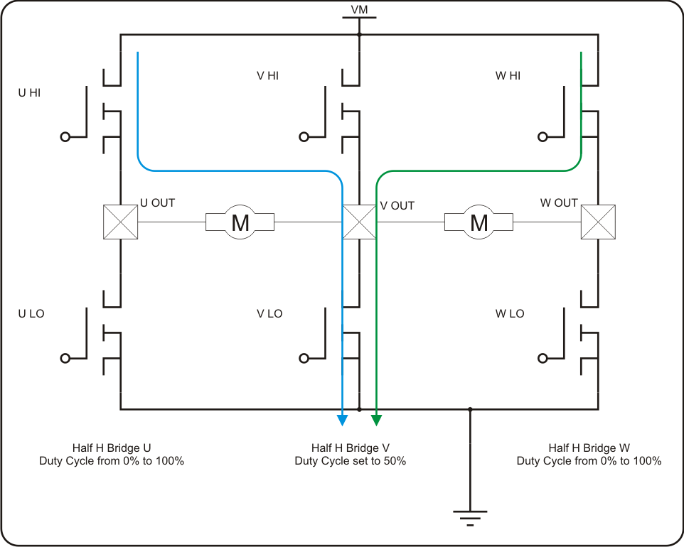
If you think about it, this is a way to control two motors with less than two Half H Bridges. So you save on two power FETs. However, do note you will lose on voltage magnitude as now each motor can only see half of the available voltage. Whereas this may seem as a disadvantage, it is actually a plus if you think of using 6V DC motors with a 12V battery! BAM! You have just created a step down voltage supply intrinsic to the motor driver!
You also lose a little resolution as the PWM duty cycle is used for both direction and speed. Had you used a full H Bridge, you would have had the full swing of voltage on a per direction basis.
Nonetheless, for the majority of applications this may be OK.
The resultant is a module which could be in charge of driving both of your motors. You could then use an Arduino or any other computing platform to control the motor driver module. This way, the robot's brain would not have to worry about motor control and driving.
Discussions
Become a Hackaday.io Member
Create an account to leave a comment. Already have an account? Log In.