 Paul Gould
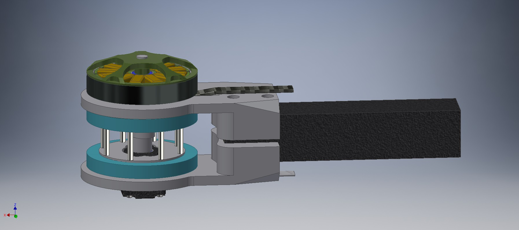
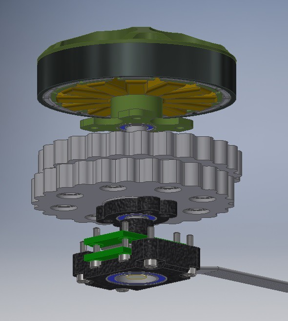
Typical Cycloidal Transmissions consist of four main sections.
- Input shaft and eccentric bearing
- Cycloidal Gear(s)
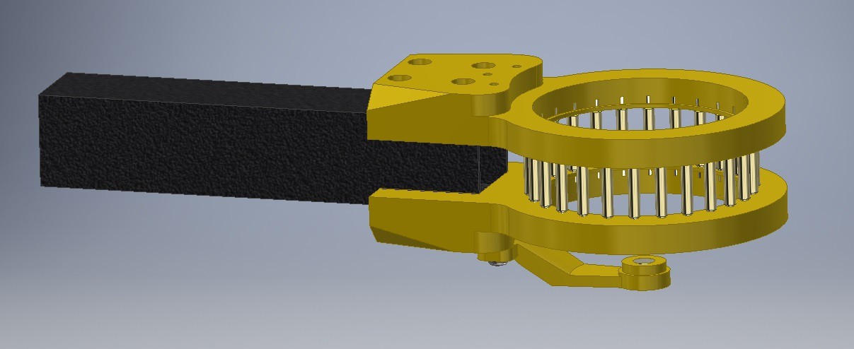
- ring pins and housing
- Output rollers and shaft
The way that the sections are arranged are with the input shaft on one side and the output shaft on the other and the housing in the middle.
https://en.wikipedia.org/wiki/Cycloidal_drive
This means that the output rollers are based on the "Fixed-Free Beam Moment" and are not suited to high torque operation when 3D printed.
This design's output support pins are based on the "Fixed-Fixed Beam Moment". This means the housing and the output rollers are dual sided. The motor input shaft is only single sided. This all works well on 3D printed parts as the forces on the steel output support pins are spread over a large area in the ABS material. A huge credit goes to Mike Buckingham for his idea on making the input shaft go through both the housing and output shaft. Sure it increased the complexity but it made the design usable.
The CAD files are uploaded to the "files page".
There are two sizes of Cycloidal Transmissions but they are identical in their design.
| Large | Small |
| Thin wall Bearing 6809 58x47x7 Hobbyking Elite 5008-330KV (6s 600W) Shaft size 6mm Eccentric offset 1mm Reduction Ratio 1:25 Cycloidal Gear "Teeth" 25 Ring Pins 26 Output Support Pins 8 | Thin wall Bearing 6807 47x35x7 Hobbyking Elite 3508-268KV HV (8s 300W) Shaft size 4mm Eccentric offset 1mm Reduction Ratio 1:20 Cycloidal Gear "Teeth" 20 Ring Pins 21 Output Support Pins 8 |
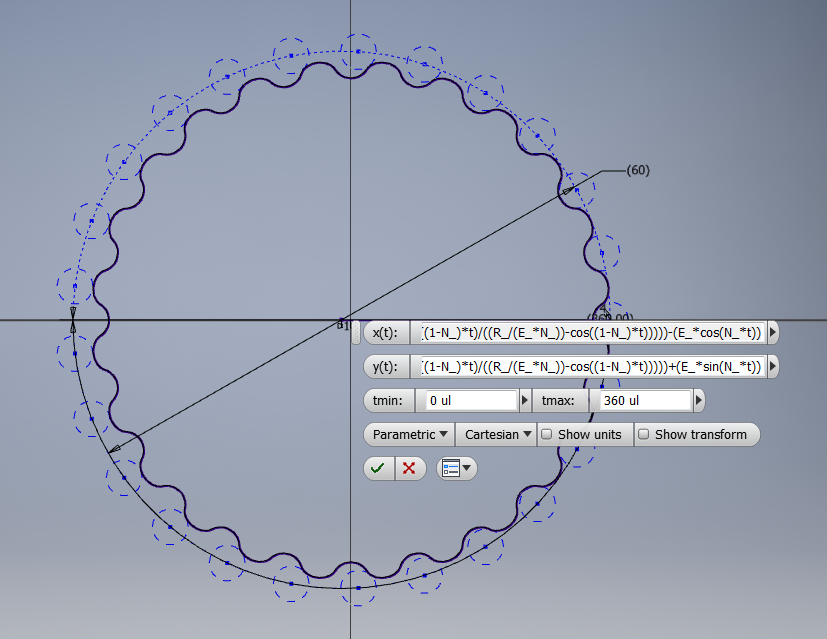
x(t) =
(R_*cos(t))-(Rr_*cos(t+atan(sin((1-N_)*t)/((R_/E_*N_)-cos((1-N_)*t)))))-(E_*cos(N_*t))
y(t) =
(-R_*sin(t))+(Rr_*sin(t+atan(sin((1-N_)*t)/((R_/E_*N_)-cos((1-N_)*t)))))+(E_*sin(N_*t))
N_ = number of rollers
Rr_ = radius of rollers
R_ = radius of Rotor
E_ = eccentricity
Discussions
Become a Hackaday.io Member
Create an account to leave a comment. Already have an account? Log In.
Excuse me. How to design this gear box? Any reference for the calculations? Thanks
Are you sure? yes | no
Hmm, looking at the parts, most of them are pretty flat, or could be made flat with small modification. I wonder if this could be laser-cut instead of 3d-printed. That would potentially allow you to use stronger materials.
Are you sure? yes | no
If you take into considerations quality of edge cut by laser (which will impact precision of such a gear) you could do it. (https://www.mate.com/technical-resources/tips-techniques/laser-cut-quality-guide/) But better option would be just cnc milling it.
Are you sure? yes | no
Sure, CNC is always an option, however, for a regular hobbyist it may be a bit too expensive or too hard to access. Laser cutters are in every hackerspace nowadays, and you can also order things online.
Also, technically speaking, both laser cutters and 3d printers are CNCs...
Are you sure? yes | no
Sure, and you can even convert cheap your 3D printer for milling purposes. All I'm saying is that if you've seen a pictures about quality of laser cut (I've posted a link to that in prev message) then it is all you can get from this technique. It is definitely not good for things that would require precise cut surface.
Are you sure? yes | no
I'm not sure, still seems more precise than a hobby grade 3D printer.
Are you sure? yes | no