 Paul Gould
The goal of the Actuator Controller is to
- Drive the Brushless motor at high speed and low speed including zero speed (holding joint position)
- Joint Position Control PID
- Actuator Communications
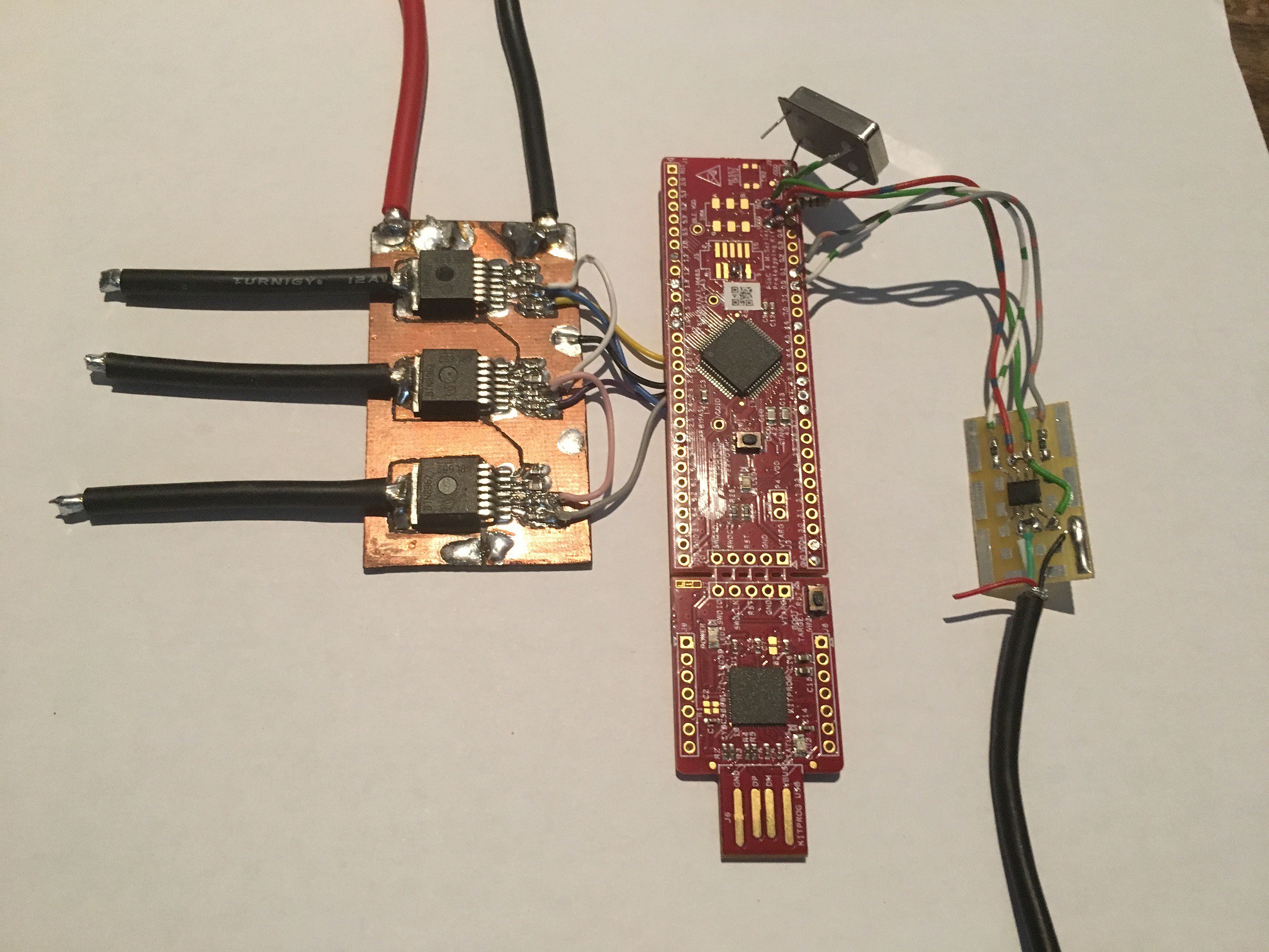
Hardware for the First Controller
- PSOC4 Development board CY8CKIT-043
- 3x Half Bridge Drivers BTN8982TA (10mOhms 55Amps 40V)
- CAN Transceiver
- Hall effect sensors for Motor commutation
- Potentiometer for Joint Position
Brushless Controller 1.0 (of many)
The control of the Sensored Brushless Motor with Hall effect sensors was done by a "look-up table" in the digital Marcocells of the PSOC4, no CPU overhead is needed for Brushless comutation. Only Direction and PWM duty cycle are passed to the Marcocells. The hall effect sensors only had a resolution of 6 phases per electrical revolution. This worked ok at high speeds but the motors operation would not be smooth a low speeds or when trying to hold a set position.
Brushless Controller 1.1
The Hall effect sensors used had a differential analogue output. In the previous control method they went into the PSOC's internal compactors. In this control method they can be read by the PSOC's differential ADC and a reasonably accurate electrical position can be calculated. Having full motor position information meant that Field Vector Control could be implemented. (More on this later)
The problem with using hall effects in this manner is that the distance between the hall effect sensor and the flux ring has a large effect on the voltage output. Also the type of sensor and thickness of the flux ring varies so much that it is not practical to use this technique for a general purpose robot actuator. For example, when used on the Multistar Elite 5008 the hall effect sensors gave a good sinusoidal output over one electrical rotation, every time took apart system and put back the Hall-effect board the amplitude of the sinusoidal output would change. Moving the hall effect sensors over to the Multistar Elite 3508, the effective diameter had to change but the sinusoidal output was very small.
I came to the conclusion that the thickness of the flux ring on the Multistar Elite 5008 was too thin or the magnets are too strong, either way it is not the most efficient design. It let too much of the magnetic strength travel on the outside of the motor. By contrast the the Multistar Elite 3508 had very little magnetic flux on the outside of the motor. This is not good for using external hall effect sensors but at least the full magnetic strength can be potentially used
Using external hall effect sensor with differential analogue to use Field Vector Control is not relieable for general use. Maybe internal hall effect sensors could work better but they would not be installed easily for different types of motors.
Brushless Controller 1.2
No more Motor based hall effect sensors. Some other brushless controllers use quadrature optical encoders but these need to be referenced on power up. I prefer absolute position sensors, so a diametric magnetic is placed on the motor output shaft and the magnetic rotary encoder chip placed opposite to it. The first chip i used was a AS5043 10-bit SSI, PWM and analogue outputs with a Max 30kRPM (10KHz update rate). This is the "Magnetic Induction" that is used in the Hobbyking HK47360TM Servos, I had several of these in one of my original quadruped robots. The AS5043 and diametric magnetic replaces the normal potentiometer in the servo. It was setup using it's analog output set to 180 degree at full scale and low noise/slow mode.
For use as a absolute angle sensor with Brushless motors a few changes were made. Slow mode was changed to Fast Mode. The SPI from the PSOC was connected the AS5043 SSI which gave a 1024 counts per revolution. With the 5008 having 7 magnetic pole pairs this meant that there were about 146 counts per electrical revolution at 10KHz sample rate. I have used this type of sensor on different Brushless Motors that have a pole count of 7 pole pairs. I'm not sure if it will be able to work with higher pole counts but for now it suits my needs.
Two AS5043 sensors can be connected in "daisy chain" by clocking 32 bits on the SPI. One AS5043 for motor commutation position and one for Joint position. This hardware set-up with Field Vector Control achieved reliable results on both 5008 and 3508 actuator systems.
The next limiting factor was the 3x Half Bridge Drivers BTN8982TA (10mOhms 55Amps 40V). They had a few issues like switching above 10Khz, operating at low and high duty cycles (long rise/fall times), inaccurate current measurements that varied between devices and they took up a lot of space. A real Brushless motor driver was required.
Discussions
Become a Hackaday.io Member
Create an account to leave a comment. Already have an account? Log In.