Paul Gould
-
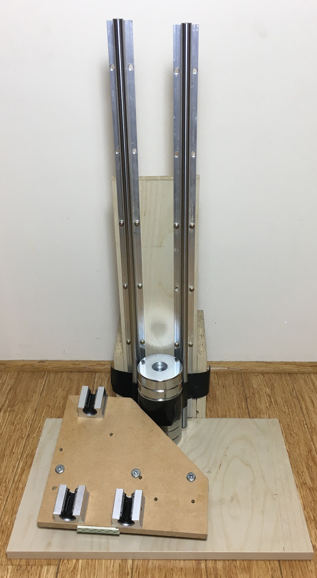
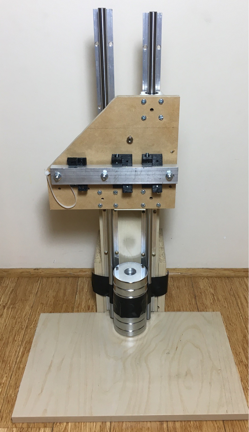
Quadruped Jump Jig
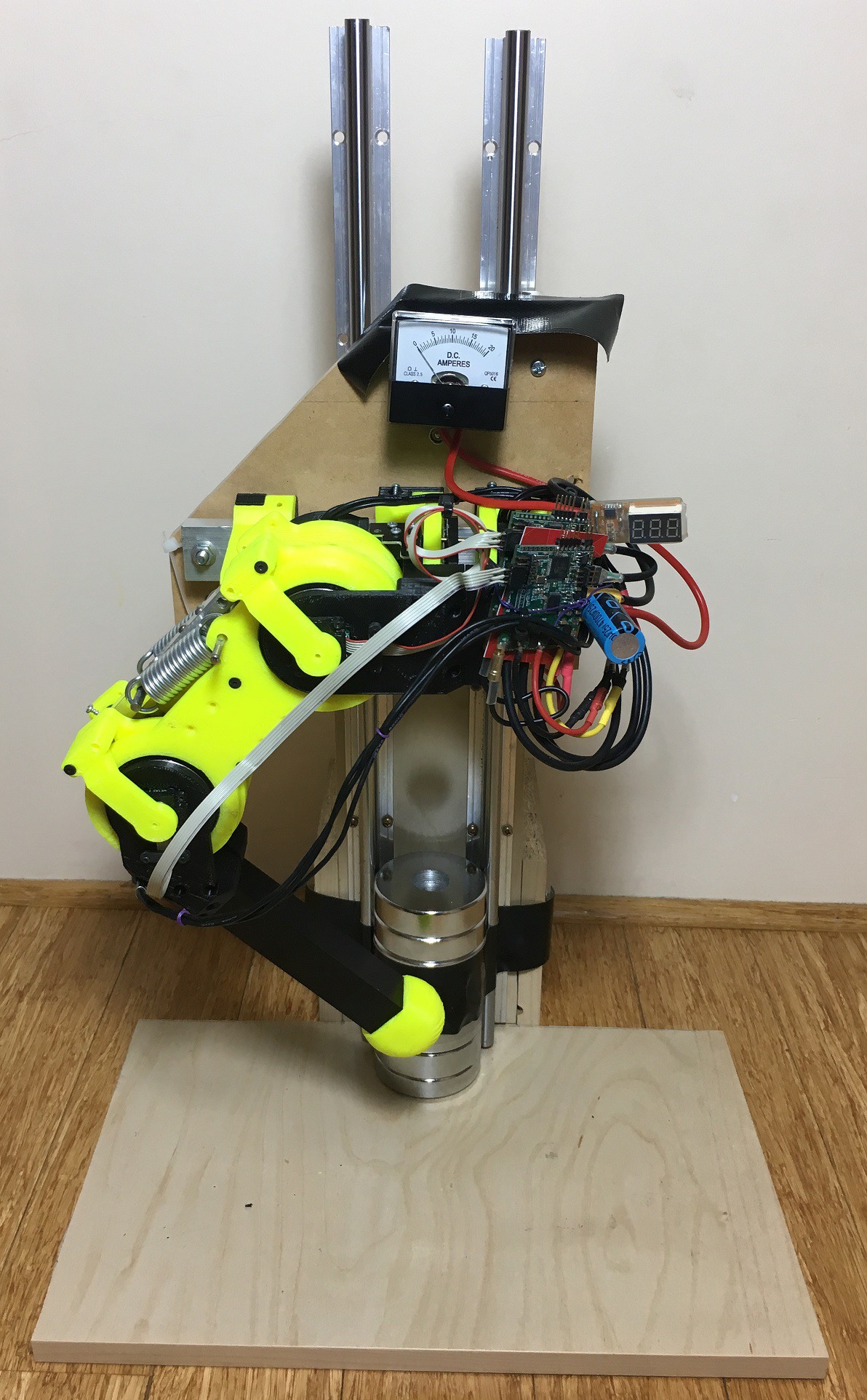
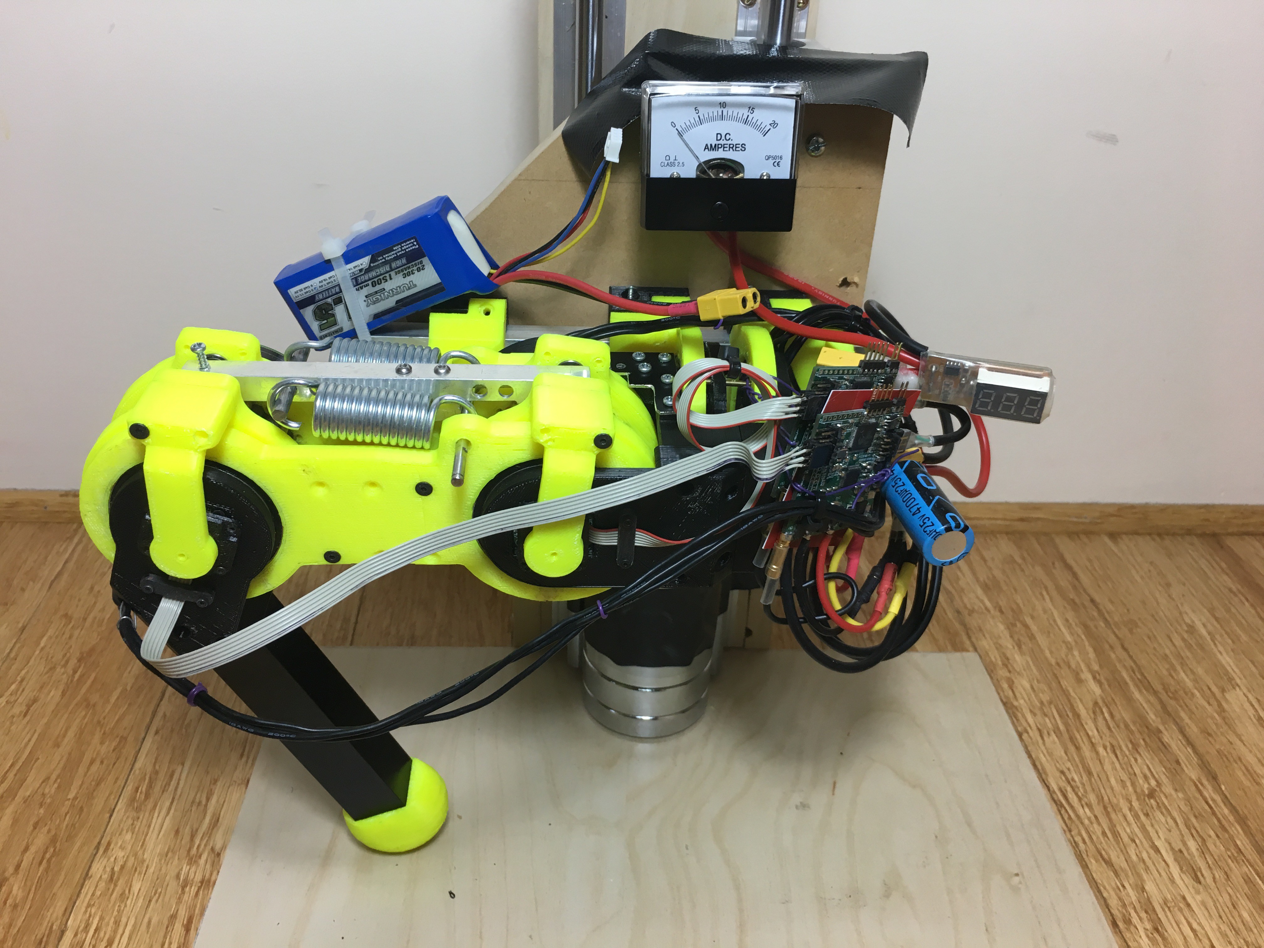
10/13/2018 at 15:42 • 0 commentsComponents
- 2x Linear rails
- 4x Linear Bearings
- wood and screws
- 11.1V 1500mAh Lipo Battery
- Analogue Current Meter 20A
- Digital Current / Voltage Meter
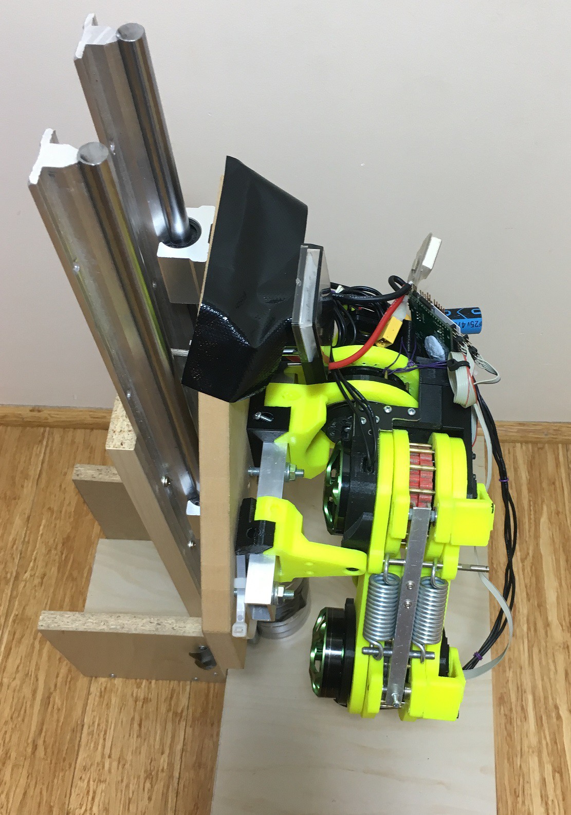
- Robot Leg
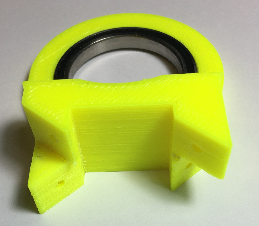
Assembly
![]()
![]()
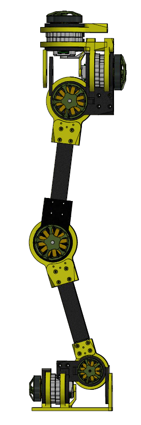
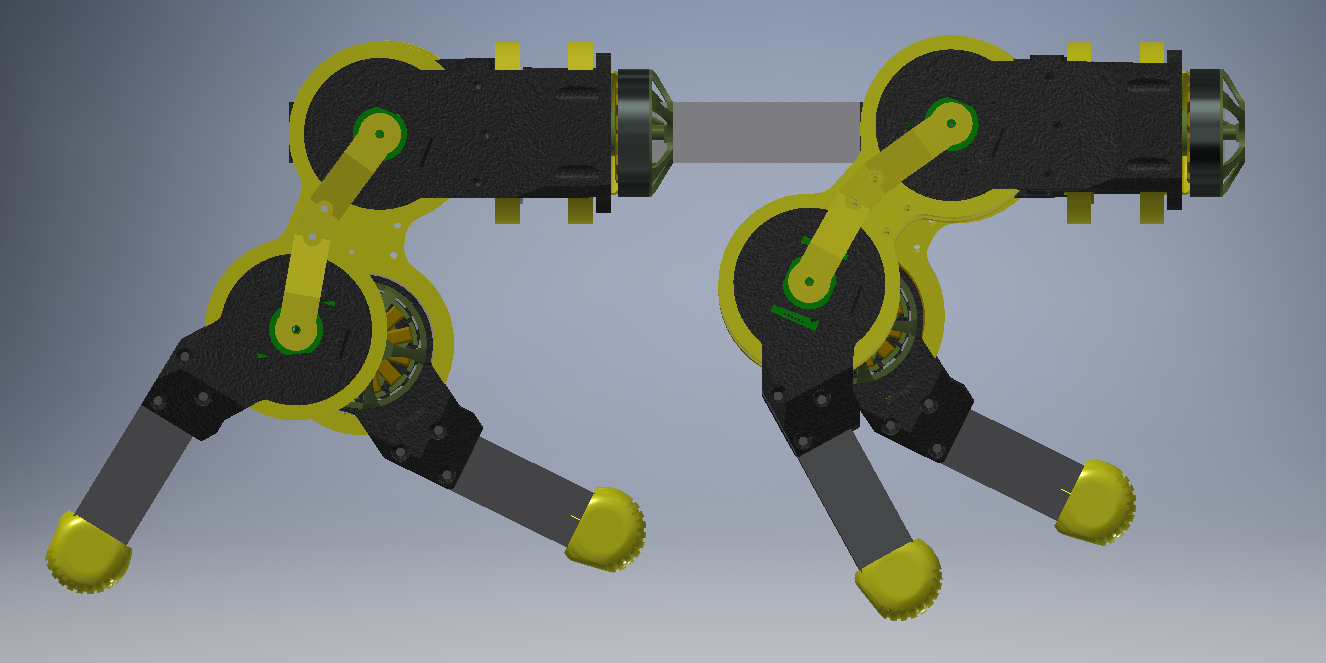
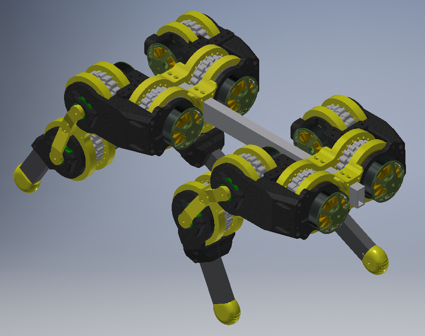
The rectangular extrusion is the same size as the quad's "backbone" and the robot's hip joins with the following design.
![]()
The robots hip has three mounting points to the rectangular extrusion.
![]()
![]()
![]()
-
PSOC4 - CAN and FLASH
10/13/2018 at 15:23 • 0 commentsThe PSOC4 and the IDE Creator helps you to write code for the Arm processor, the CAN peripheral and the FPGA logic. When you use it for standard operations, then you rarely need to go deep into the component datasheets to make the design work as required. The examples are quite useful.
But, if you want to design something that is not normal, then it is hard to find the information required.
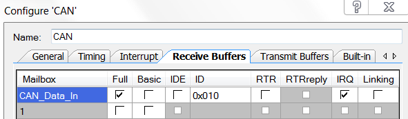
CAN Problem
Each Actuator needs to have it's own individual address or CAN IDs. In my robot there will be at least 12 actuator controllers that will be CAN slaves, with one controller configured as a CAN master. This requires setting the CAN Receiver Mailbox ID via software. It is normally done in the .cysch CAN configuration page.
There is a easy for setting the Transmit message ID.
CAN_SET_TX_ID_STANDARD_MSG(0,(TX_ID));There was no such sub-routine for the setting the RX message ID. So after a lot of reverse engineering and some trial and error, the following code is used. Set different IDs for each actuator.
CY_SET_REG32((reg32 *) (CYREG_CAN0_CAN_RX0_ACR), (0x0200000u*ID));This only works for Message Mailbox 0 and is good for my current needs. A second mailbox maybe required in the future that will be a broadcast message so all the receiver message Mailbox IDs will be the same. This could be used for an Emergency stop message. Send one message and all the actuators stop.
Additional CAN information
If the RTR in the Configure 'CAN' is enabled, the CAN transmitter will re-transmit the current packet until the received sends an Acknowledge packet back.
FLASH Problem
As each Actuator needs to have it's own individual ID, this value and some others needed to be stored in flash memory. But when the PSOC4 software is updated it erases ALL of the standard FLASH. It also does not have EEPROM. It has an emulated EEPROM but again this is erased after updating the program. The PSOC4 I'm using has user FLASH but there is no information on how to use it.
The set-up code is
#include <CyFlash.h>

#define CY_TEST_USER_FLASH_ROW       (CY_SFLASH_NUMBER_USERROWS - 1u)
#define CY_TEST_USER_FLASH_ADDR      (CYREG_SFLASH_MACRO_0_FREE_SFLASH0 + CY_TEST_USER_FLASH_ROW * CY_SFLASH_SIZEOF_USERROW) //255
uint8 Flash_User_Array[CY_SFLASH_SIZEOF_USERROW];
To Read from FLASH, I set up a RAM array the same size as a FLASH row.
    uint16 i;
    for (i = 0u; i < CY_SFLASH_SIZEOF_USERROW; i++)
    {
        /* Define source value */
        Flash_User_Array[i] = (*((uint8 *) (CY_TEST_USER_FLASH_ADDR + i)));
    }
To Write to FLASH, I set up a RAM array the same size as a FLASH row.
cystatus returnValue = CYRET_SUCCESS; returnValue = CySysSFlashWriteUserRow(CY_TEST_USER_FLASH_ROW, Flash_User_Array); -
Arduino Brushless FOC Controller
06/18/2018 at 14:04 • 2 commentsIn an effort to make the controller accessible to more makers I've strated designing an Arduino based system. It uses the SAM D21 G 32-bit micro-controller as used on the MKRZERO board. This chip has an advanced Timer Counter Controller which can generate three centre aligned PWM signals. After sorting out the correct pin mapping it is up and running.
![]()
The code is based on information provided in the Arduino forum by MartinL.
https://forum.arduino.cc/index.php?topic=346731.0
Now with deadband
I will create a github shortly
Next up dual SPI. One for the absolute magnetic encoder sensors and the other for the FET gate Driver IC.
PID and FOC should be easily ported across.
Voltage and current measurement may be difficult because the Arduino doesn't support free running sequential ADCs very well.
The SAM D21 does not have CAN commucations so it will need RS485 and USB.
-
Biped Design
06/09/2018 at 15:22 • 1 comment6x Actuators
Do all the joints need the same size actuators?
Are different reduction ratios required? Higher torque less speed.
-
Mini Quadruped Design (CAD)
06/08/2018 at 16:16 • 0 comments12x Mini Actuators
Needs a head, tail, electronics and batteries.
Two leg has been 3D printed. Some assembly required. See end of YouTube video. It's the little one on the left.
I have made some 2 axis legs for testing. They have enough torque but the speed is huge, even under load. Jumping is not impossible.
-
Robot Quadruped Tail
06/08/2018 at 15:41 • 0 commentsTail Design
3x Mini Actuators (5 Joints)
Joint 1 is tail "wag"
Joint 2 has figure 8 pulley to Joint 3 and the angle is opposite
Joint 3 is actuated up/down
Joint 4 is actuated up/down
Joint 5 has a figure 8 pulley to Joint 4 and the angle is opposite
Distance between Joints is 100mm
Motors are Multistar Elite 3508
The tail is used for the quadruped's balance.
Was thinking about putting an end effector, camera or gripper
-
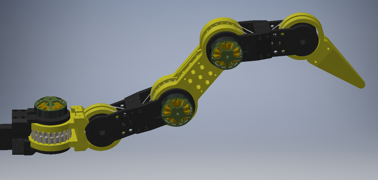
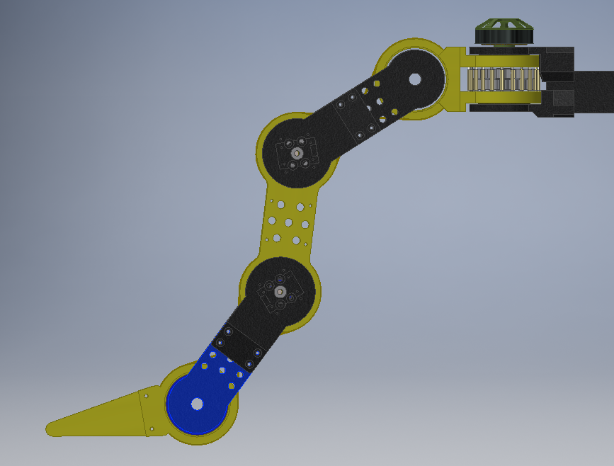
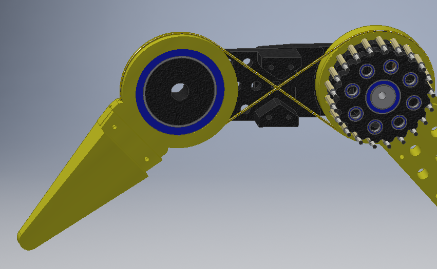
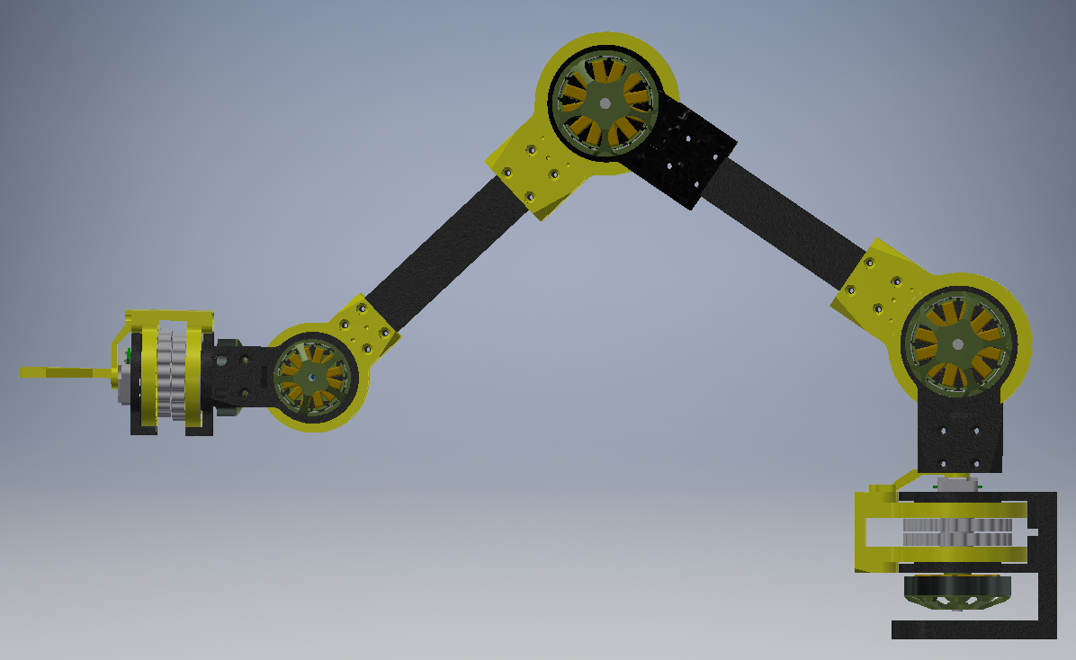
Robot Arm Design
06/08/2018 at 14:38 • 0 commentsRobot Arm
3x Large Actuators
2x Small Actuators
1x Gripper ???
Based on previous testing, it should be able to lift 0.5kg at the end effector.
-
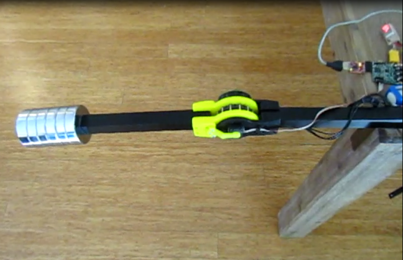
Actuator Testing
06/01/2018 at 15:31 • 0 commentsTesting using the Brushless motor, Cycloidal gearbox, Position sensors, Controller and LiPo Battery
- 3kg of weights placed at 330mm distance from the center axis = 100kg/cm or 10Nm
- The laptop sends a command to move between 90 (vertically down) and 180 degrees (horizontal)
- 11.1V 3Cell LiPo (1500mAh 30C)
- Peak Current while moving is about 6A @ 12V = 60W
- Controller is set to 50% max PWM (I don't want to break anything yet)
- 90degrees transit time is about 1 second @ 10Nm load
My prototype actuator has a tested no load speed of 60deg in 0.2sec @ 12V, 4A @ 50 Max PWM
I have not tested the max stall torque but 10Nm is currently suitable for my needs.
The motor can handle 600W (22V @ 27A) and the brushless controller can handle 4000W (40V @ 100A) (both dependent on cooling)
In comparison, the Dynamixel MX-106R is the servo I wanted as it had 100kg/cm (10Nm) stall torque but it's no load speed is 55RPM and it cost ~US$500
-
PSOC4 Controller software
05/16/2018 at 15:03 • 0 commentsThe software runs on the PSOC4 by Cypress and is a Programmable System on Chip which includes
- 32-Bit ARM Cortex M0 (48MHz)
- Programmable Digital Blocks - UDB (Like FPGAs)
- Programmable Analogue Blocks (Opamps, Comparitors, ADC, DAC)
In the PSOC4 you can choose between fixed blocks (as in normal micro-controllers) or Universal Digital Blocks (as in FPGAs). So features like SPI, I2C, UART, Timers and Counters (PWM), can be either fixed or custom.
I was hoping to say that is it fully configurable but it is really not. There are many limitations and work-arounds in both hardware and software. That being said, it is a brilliant chip, you can do many things without the CPU being involved at all. The sequencing SAR ADC is a good example of this. The IDE is good but hides too much low level functions. Things like being able to change the CAN ID on the fly meant searching through lines of undocumented c code.
The software/configuration went through many iterations depending on the Controller version.
Software Structure for Brushless Controller 2.0
- Restore Configuration data from User Flash
- Create Sin array from number of motor pole pairs
- Configure Motor Driver
- Enable Everything (Comms, PWM, ADC and IRQ)
- The Sequencing ADC End of Conversion IRQ is the sub-routine for the controller loop
- Read Motor and Joint position information
- Read ADC information (Current, Voltage, Temp)
- PID
- Field orientated Control (FOC)
- Sin to PWM output
- CAN IRQ
- Motor Fault IRQ
- UART Debug Control and User Flash Configuration
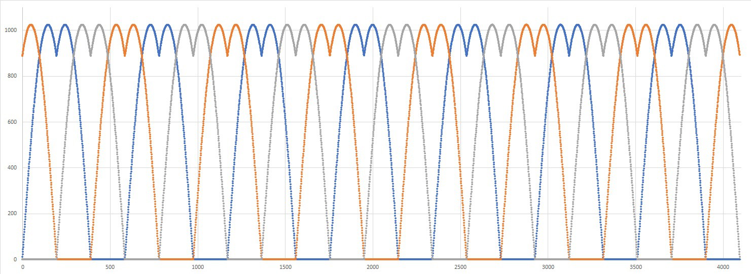
The sub-routine for the controller loop runs at 10kHz and uses about 20% of the CPU time. Not bad for a 48MHz CPU and doing FOC. The main reason it runs efficient is the that FOC array is pre-calculated to suit the number of poles of the motor being used. The other two phases are just offsets in the main array. The output from the PID is just a multiplied by the FOC array and shifted to get the three PWM signals. There are no sin and division calculations in the controller loop.
![]()
The FOC array is based on modified sinusoidal waveform, often called saddle profile. It has the benefits of higher voltages between phases (than pure sin waves) and 1/3 less switching losses. The FOC array has 4096 (2^12) points and the Motor's Magnetic encoder has 16384 2^14 steps. Which is fine, because the encoder has some noise.
The hardware and software has been updated to the "file page".
-
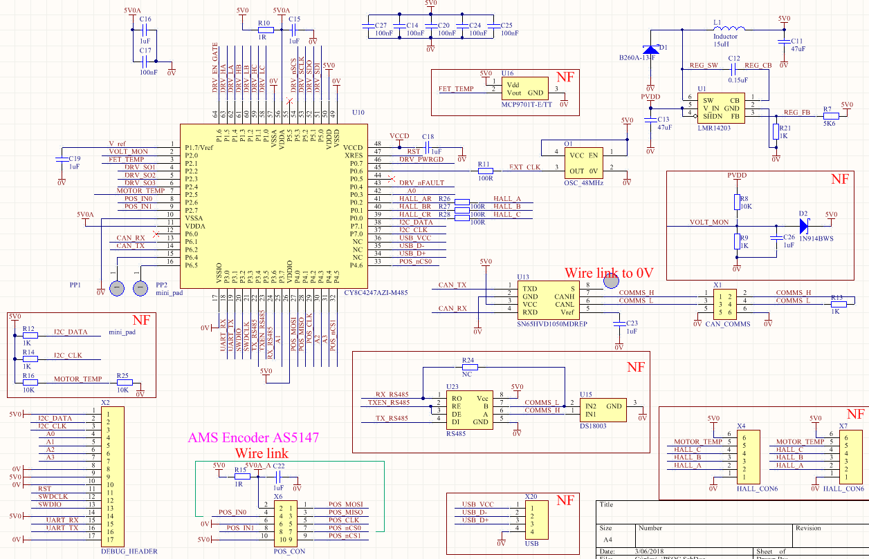
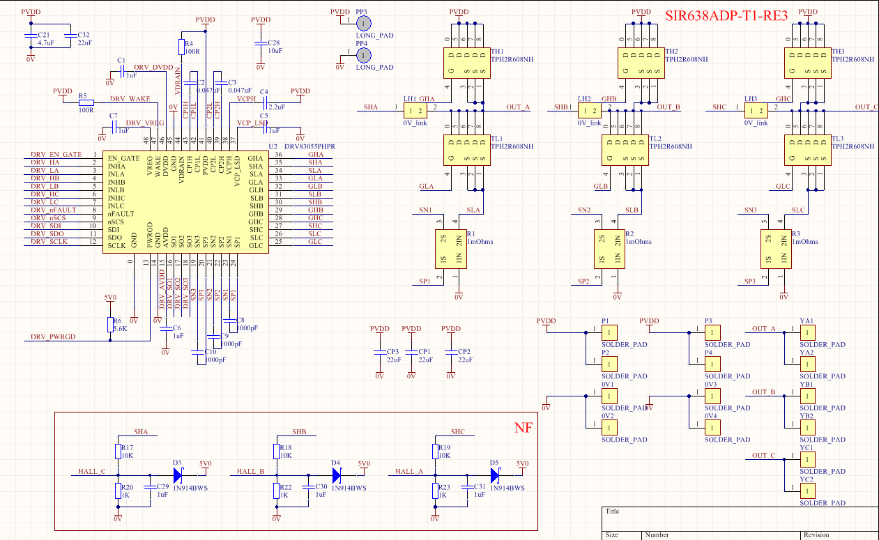
Actuator Controller - Hardware
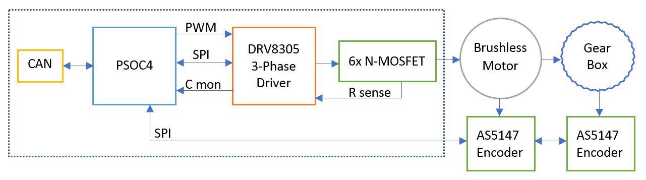
05/13/2018 at 15:03 • 2 commentsFrom everything that was learnt from the hardware development a real / custom actuator had to be developed. After some research the best/easiest solution for me was the 3-Phase driver DRV8305 paired with 6x N-MOSFETs and the PSOC4 Processor.
Hardware for the Second Controller
- Custom 4 Layer PCB 47mmx45mm
- PSOC4 CY8C4247AZI-L485 ARM Cortex-M0 32-bit Processor with Programmable Analog Block and Programmable Digital Blocks
- DRV8305 MOSFET Driver with integrated Current Sense Amplifers, SPI and PWM Control
- 6x N-MOSFETs R-on-typical @ 0.7mOhms 40V
- 3x 1mOhms Current Sense Resistors
- CAN Transceiver
- 25MHz Oscillator
- LMR14206 Step Down Regulator
- Optional (un-populated) - RS485, FET Temp Sensor, USB, Hall effect input, Sensorless operation
![]()
Brushless Controller 2.0
There is not much to say about this controller. All components were "wired" up as per their datasheets. As the two main IC's have a lot of integrated components inside there is not much interconnects required.
![]()
The angle of the motor and the joint is read by the AS5147s via SPI. PSOC4 uses PID to determine the required joint position and uses Field Orientation Control from motor angle to calculate 3 Sinusoidal values. These Sinusoidal values are converted to PWM signals to drive the 3-phase Driver. This intern drives the 6x N-MOSFETS to power the Brushless Motor. Control of the Actuator is done by CAN.
As the board was soldered by hand, the SPI link between PSOC4 and the DRV8305 helped to to pick up dry-joints and short-circuits on the MOSFETs, Current Sense Resistors and some DRV8305 pins. It had many fault and error registers which points directly to the bad connection.
The Schematic and PCB has been uploaded to the "file page".
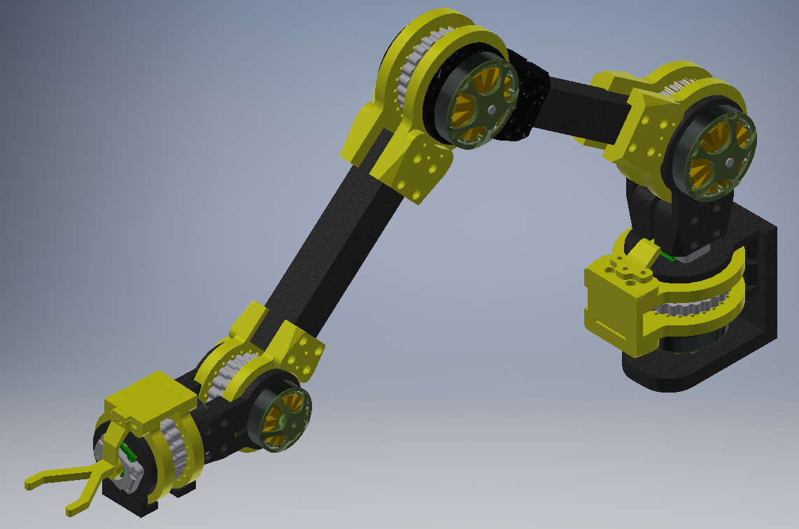
3D Printed Robot Actuator
A high speed and high torque robotic actuator using low-cost brushless motors, custom controller, 3D printed parts and bearings.