0%
0%
Sphere of Light
Build your very own disco ball with some ninja soldering skills a little help from the 3d printer
 Hexabitz
Become a Hackaday.io member
Already have an account? Log in.
Just one more thing
To make the experience fit your profile, pick a username and tell us what interests you.
Pick an awesome username
hackaday.io/
Your profile's URL: hackaday.io/username. Max 25 alphanumeric characters.
Pick a few interests
Projects that share your interests
People that share your interests


 SimonXi
 amiravni
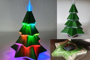
 makeTVee
this looks really lovely. i cannot wait to build one. thanks for sharing!