 kabir.plod
-
1Programming the NodeMCUs
The writeups here are phrased more as project logs than directions for replication. I'm not using the logs section because I can't insert logs back in time to patch steps I forgot to document in the build process. Nevertheless, there should be enough detail here to make the buzzers yourself.
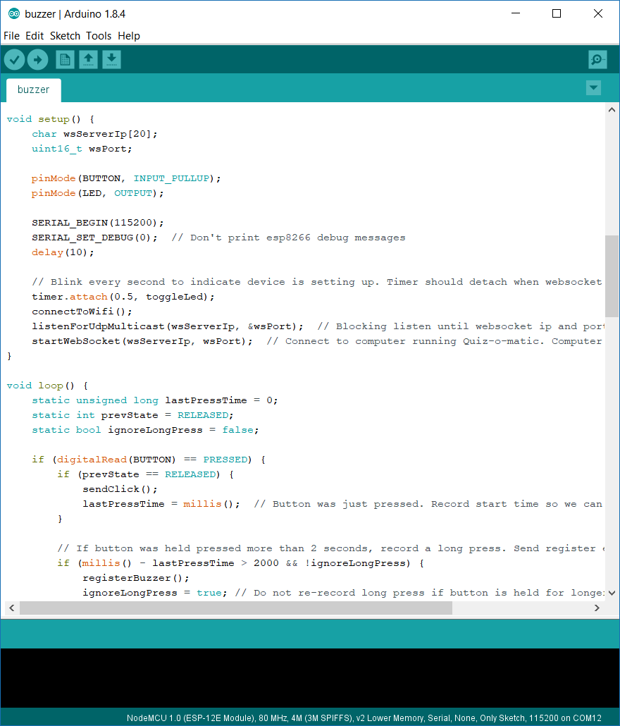
The NodeMCUs arrived in about 14 days using AliExpress Standard shipping. Upon receiving them, I set up the Arduino IDE to be able to flash them using mainly this video tutorial. I read through this guide to get up to speed with its capabilities. The documentation and examples on github were quite clear. I also added the arduinoWebSockets library (Sketch > Include Library > Add .ZIP Library) so that the program could communicate with the desktop application I had previously coded over websockets. Websockets provide a persistent connection over TCP. Data sent over websockets theoretically has a lower latency than an HTTP request with the same payload, since a persistent connection is opened, though I haven't tested it for this application.
![]()
My initial attempts to flash the NodeMCU were met with the error
error: espcomm_open failed
error: espcomm_upload_mem failed
Some quick googling indicated that I had to enable flash mode on the board: hold the flash button, tap the reset button, and finally release the flash button. -
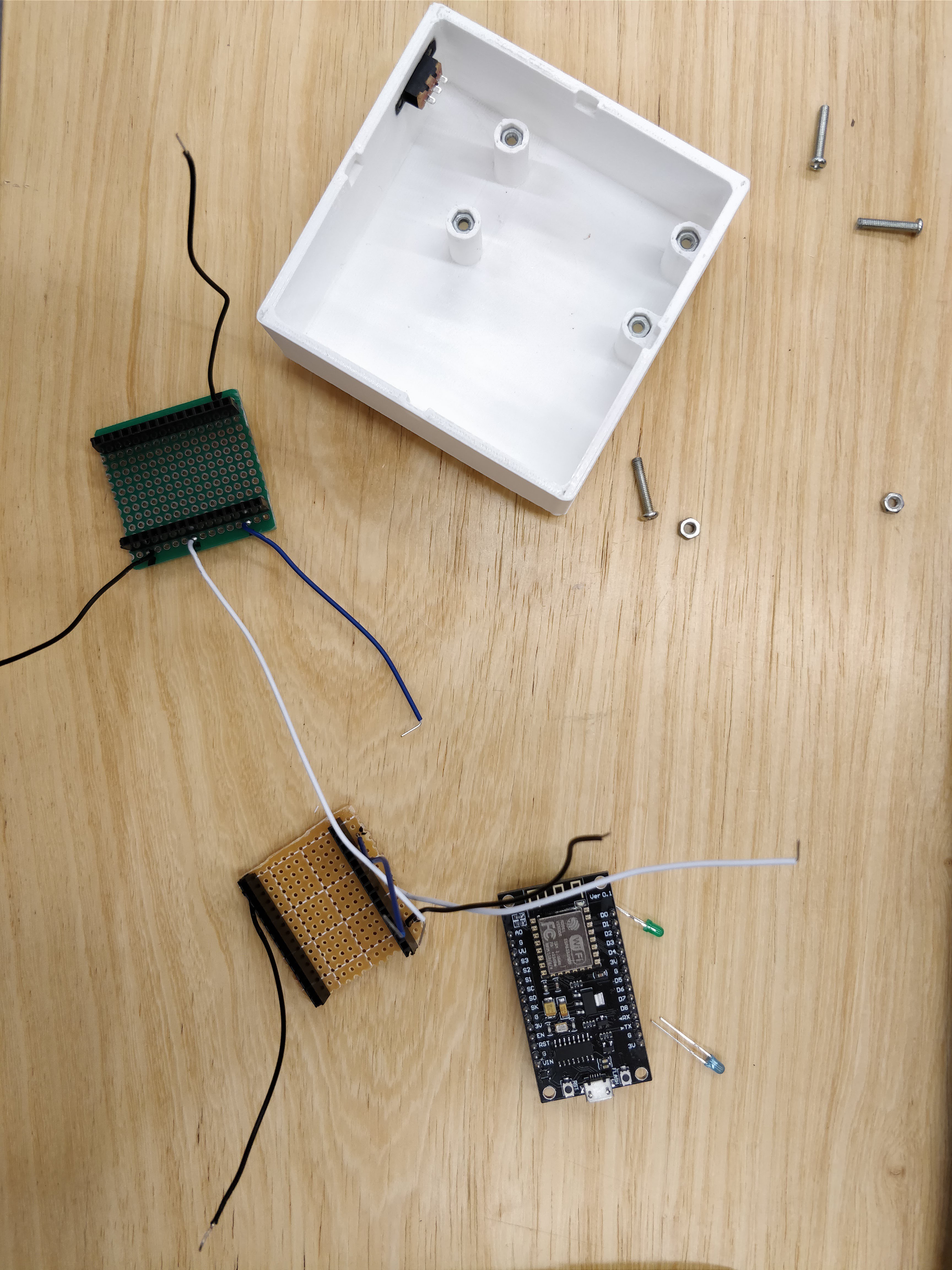
2Breadboarding
![]()
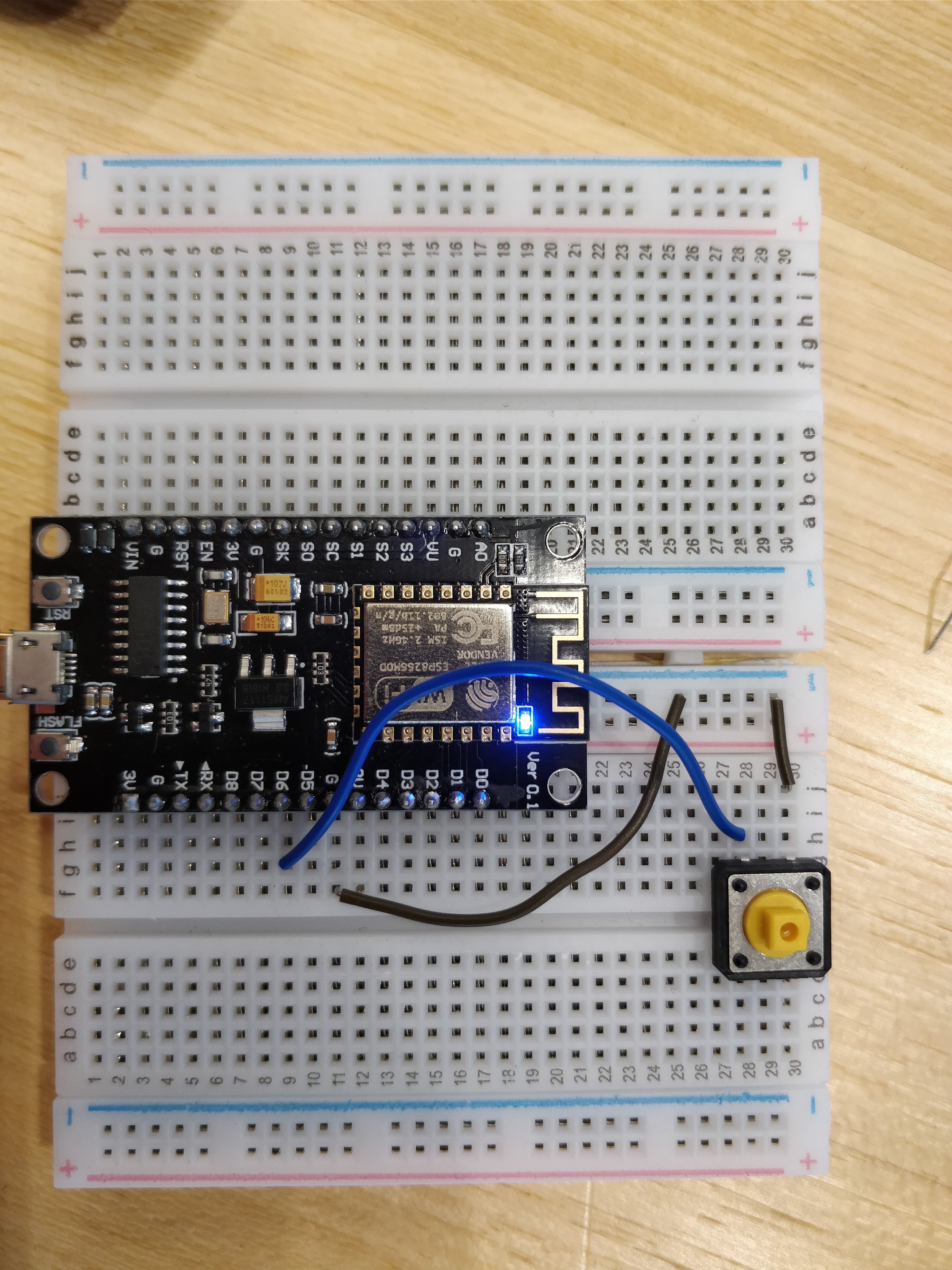
Annoyingly the NodeMCU required 2 breadboards to mount. I hear that this a problem with v3, as v2 has a smaller form.
The first problem was finding the laptop's IP address so that the board could talk to it. I looked into a few protocols for device discovery on a local network, including mDNS, UPnP and SSDP, but couldn't find a drop-in library for a C# application. Instead, the desktop program multicasts UDP packets every 2 seconds to advertise its IP address and the port of the websocket server (inside the packet contents). When the NodeMCU receives a signal, it connects to the websocket at the sender's IP address and the port specified. Any subsequent messages are sent over this persistent connection. Afthe NodeMCU connects to the websocket server, the LED on the board stops blinking to indicate successful setup. Note that the PC and board have to be on the same network for this work.
A push button was connected to GPIO pin 12 (D6) and configured to use an internal pullup resistor. Using a pullup meant that the button pressed state was logic low and released state logic high.
So that the board could recognize both short and long presses, I opted to use polling logic over interrupts. This method is easily extensible to record double clicks as well. While interrupts would allow the ESP8266 to sleep, this application is unable to take advantage of the low power modes since all of them disconnect from wifi. Reconnect time is on the order of seconds. And polling is easy to implement.
While a typical mouse click only records a click after the button has been released, the buzzer records one as soon as the button is down, to reduce perceived latency. A long press is recorded if the button is held down for more than 2 seconds.My goal was sub-100ms latency from a 10m distance so that teams further away don't appear on the screen after teams close by that buzzed in later (wireless mice seemed to have this problem). Preliminary tests in a WiFi-congested environment indicate a round trip of ~60ms, well within the project constraints.
See project files for the NodeMCU code, and the github repo for the desktop app code.
-
3Designing the button cap
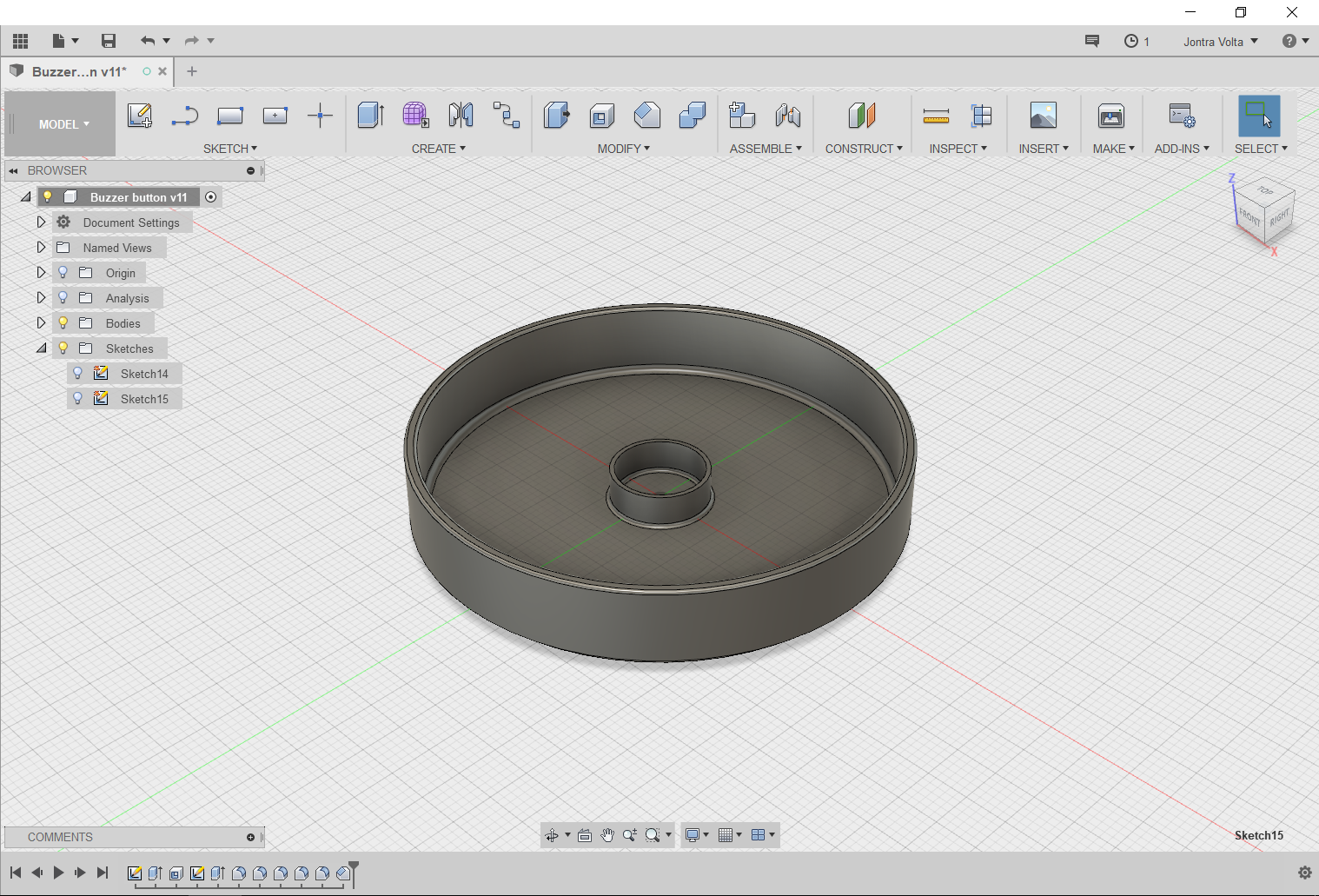
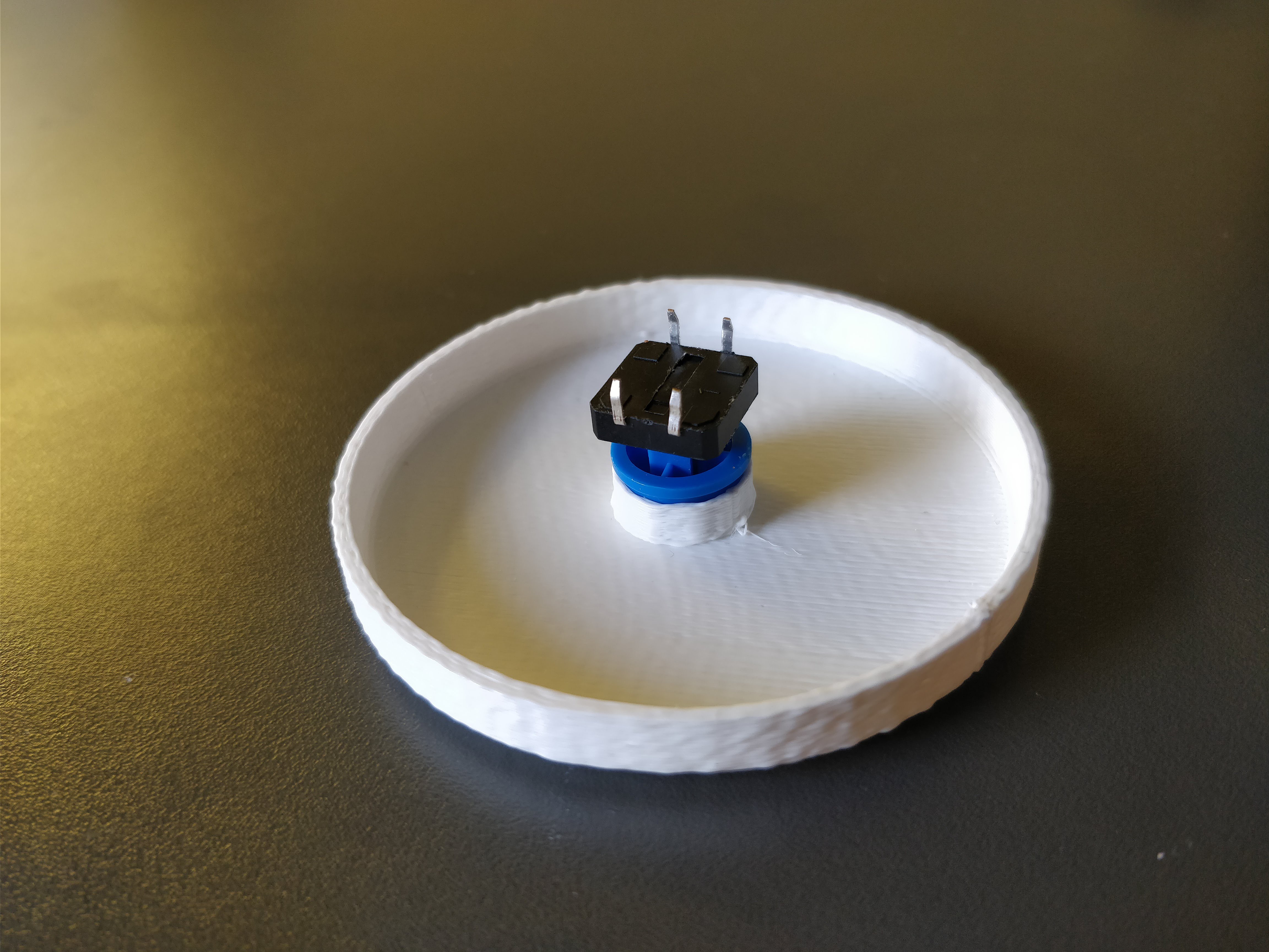
An important part of the quiz experience is smashing the buzzer button when you figure out the answer. Typical 10mm diameter buttons weren't going to cut it because they're too small for the satisfaction. Sizeable arcade buttons weren't available cheap locally or online (except, of course, the trusted AliExpress). I didn't want to wait another 2 weeks for shipping, so I decided to 3D print a 60mm diameter button cap for a momentary push button I found in the lab.
![]()
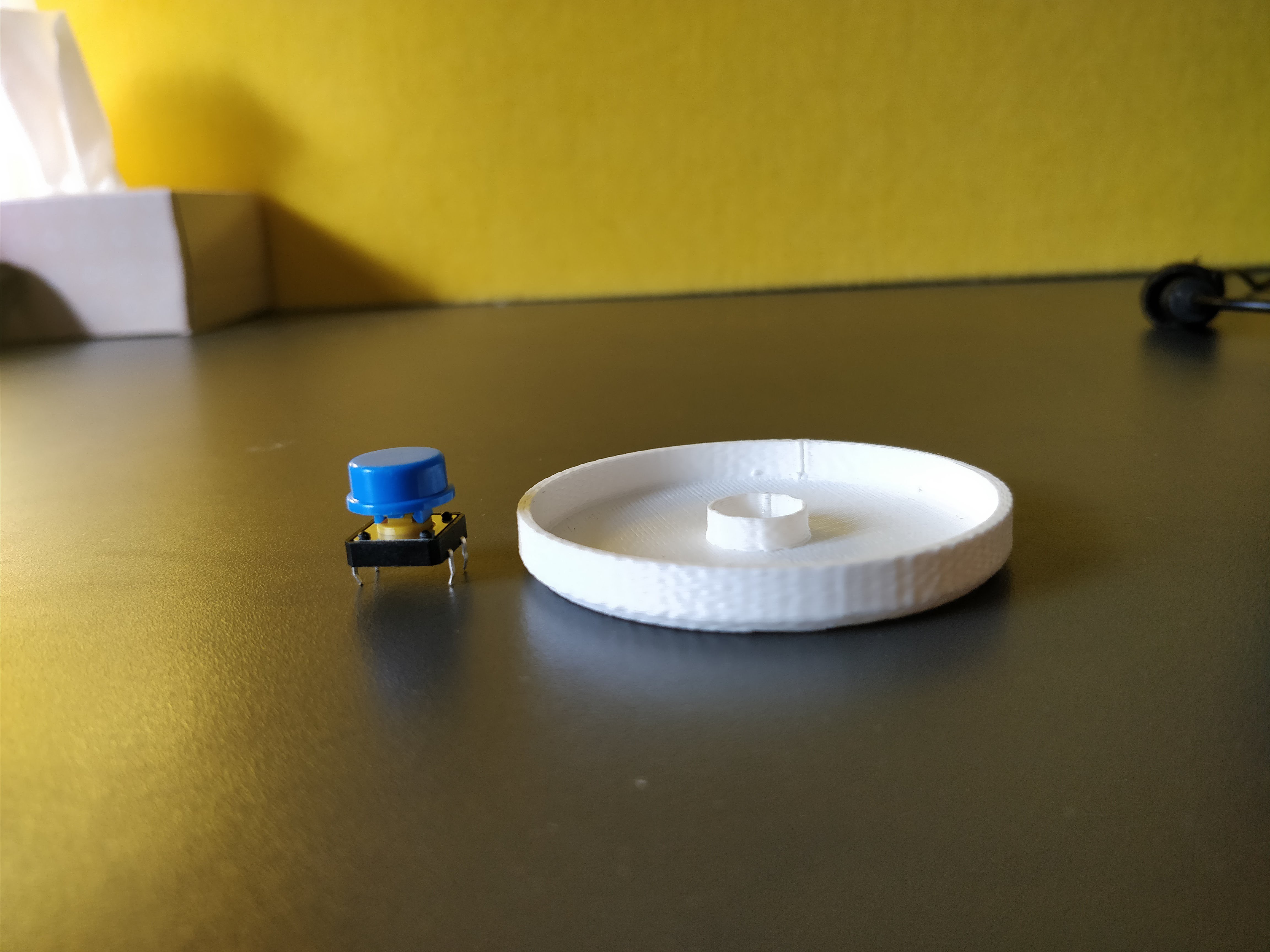
It was my first time 3D printing using a Makerbot Replicator+ at the university. I read several articles on the excellent 3dhubs.com to understand how FDM printing worked, as well as techniques and common pitfalls. Modeling using Autodesk Fusion 360 was fairly easy to pick up using this tutorial and simply playing around. It took 2 prints to get the tolerance for the cylinder fit right (0.2mm greater than button diameter).
There fillet at the base of the inner cylinder makes it a little less prone to tear off. The other fillets and chamfers are just for aesthetics :)![]()
![]()
In the first prototype the cap height was about 6 mm, whereas the final version is about 10 mm. This is due to changes in the lid design, which I will detail in the next step. -
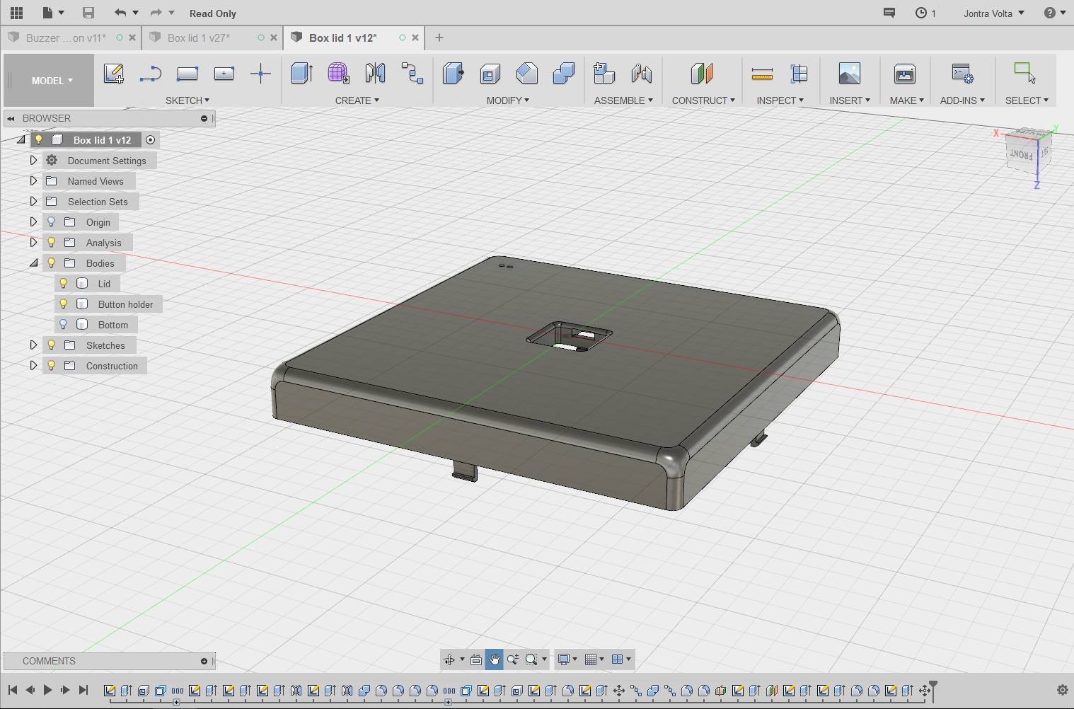
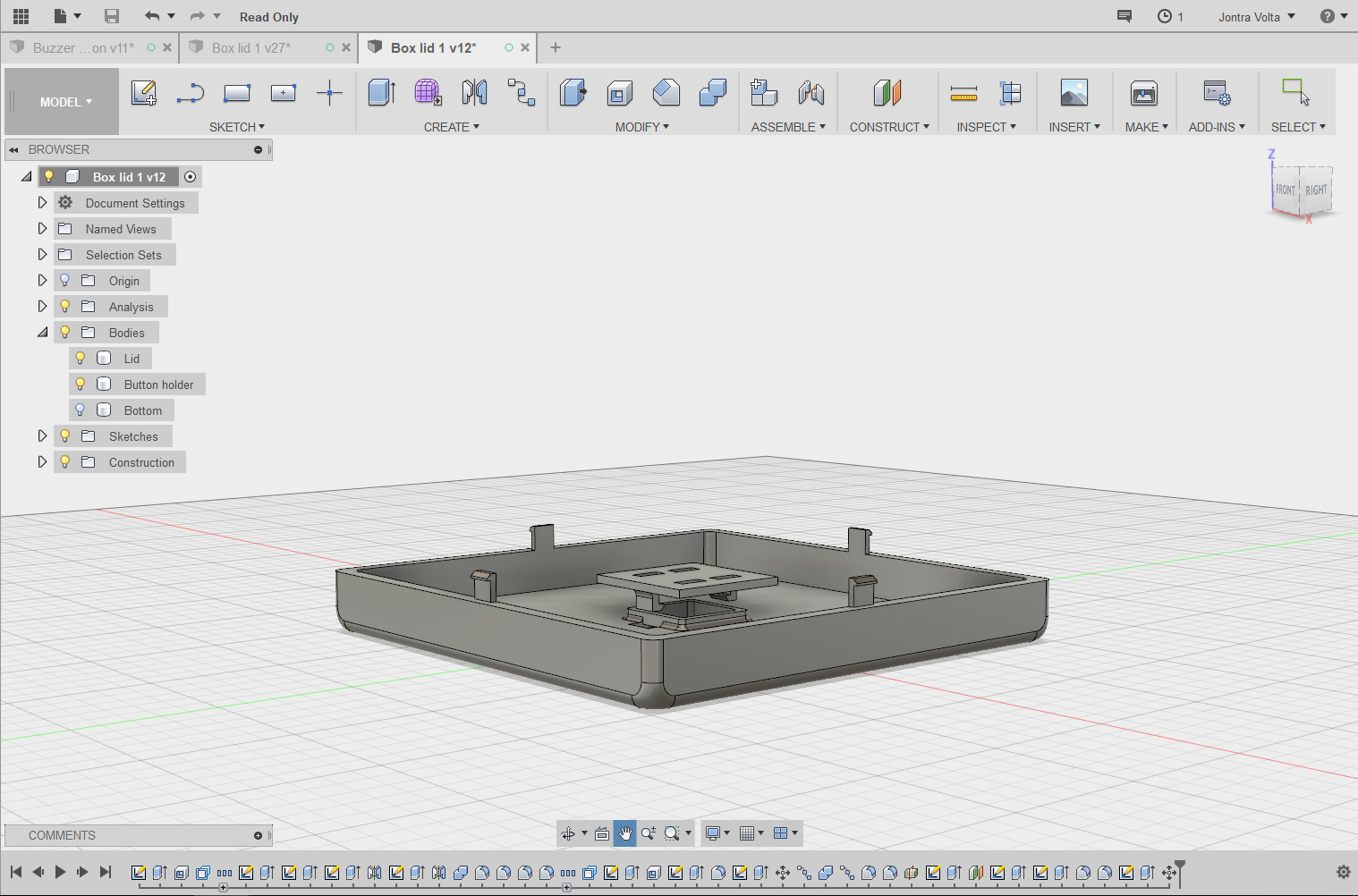
4Lid design, part 1
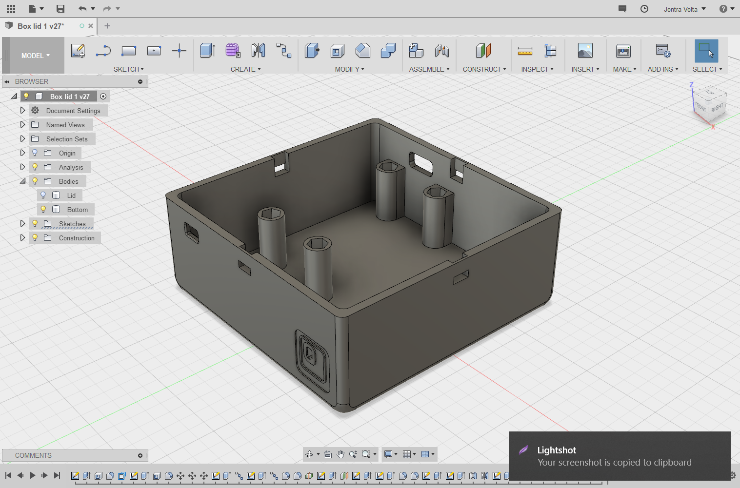
I wanted a design where the push button would sit in a recess in the centre of the lid, just for the aesthetic. The idea was there would be very little gap between the button top and the surface of the lidto make it feel more like an arcade button.
Since FDM printers don't do well with bridges, I designed a separate button bottom holder that would snap fit onto the lid. These articles were a great help in designing the enclosure and fits.
![]()
![]()
![]()
-
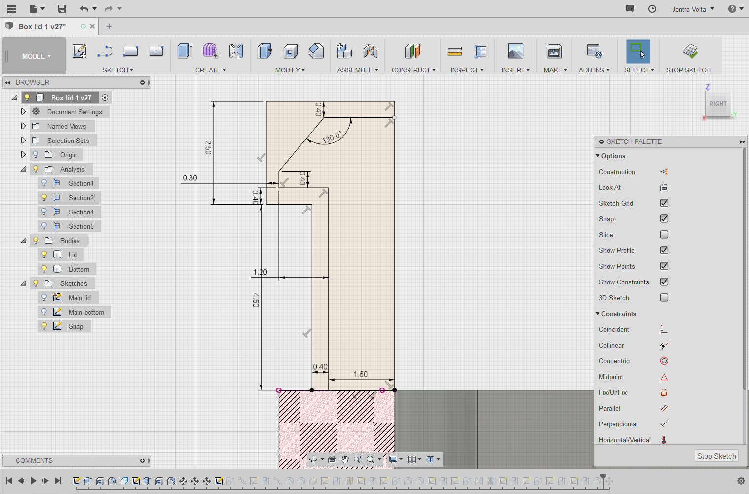
5Lid design, part 2
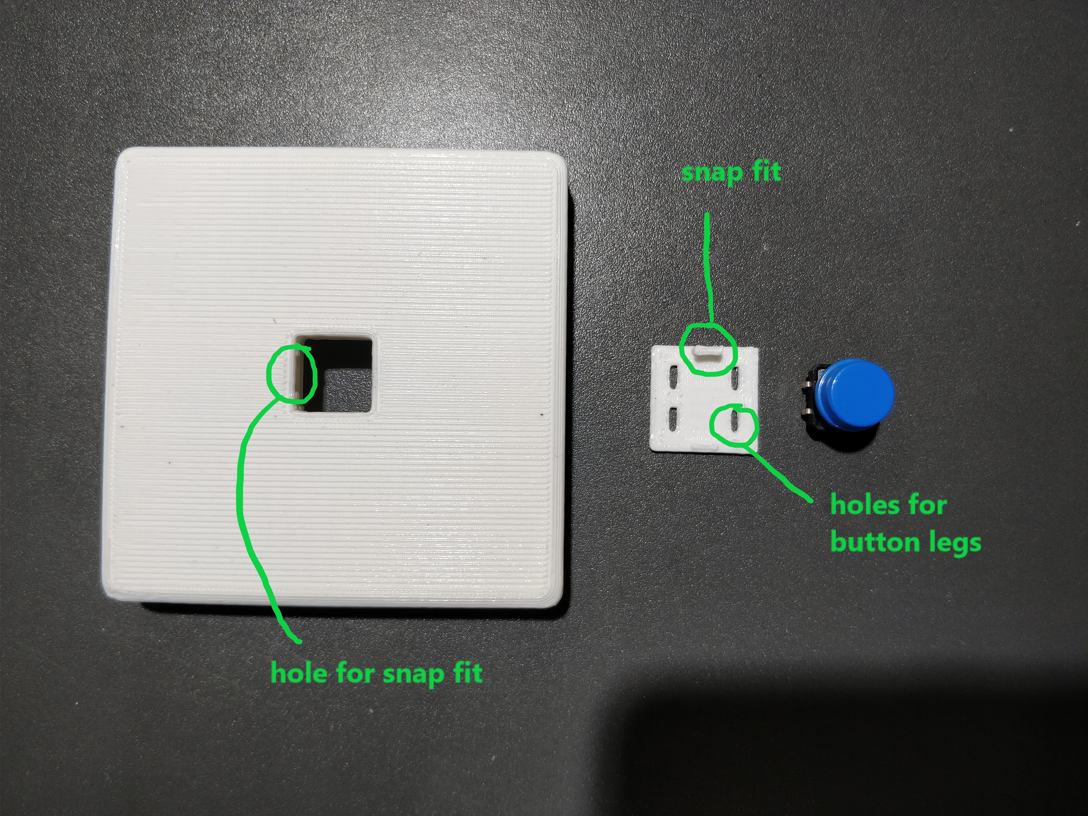
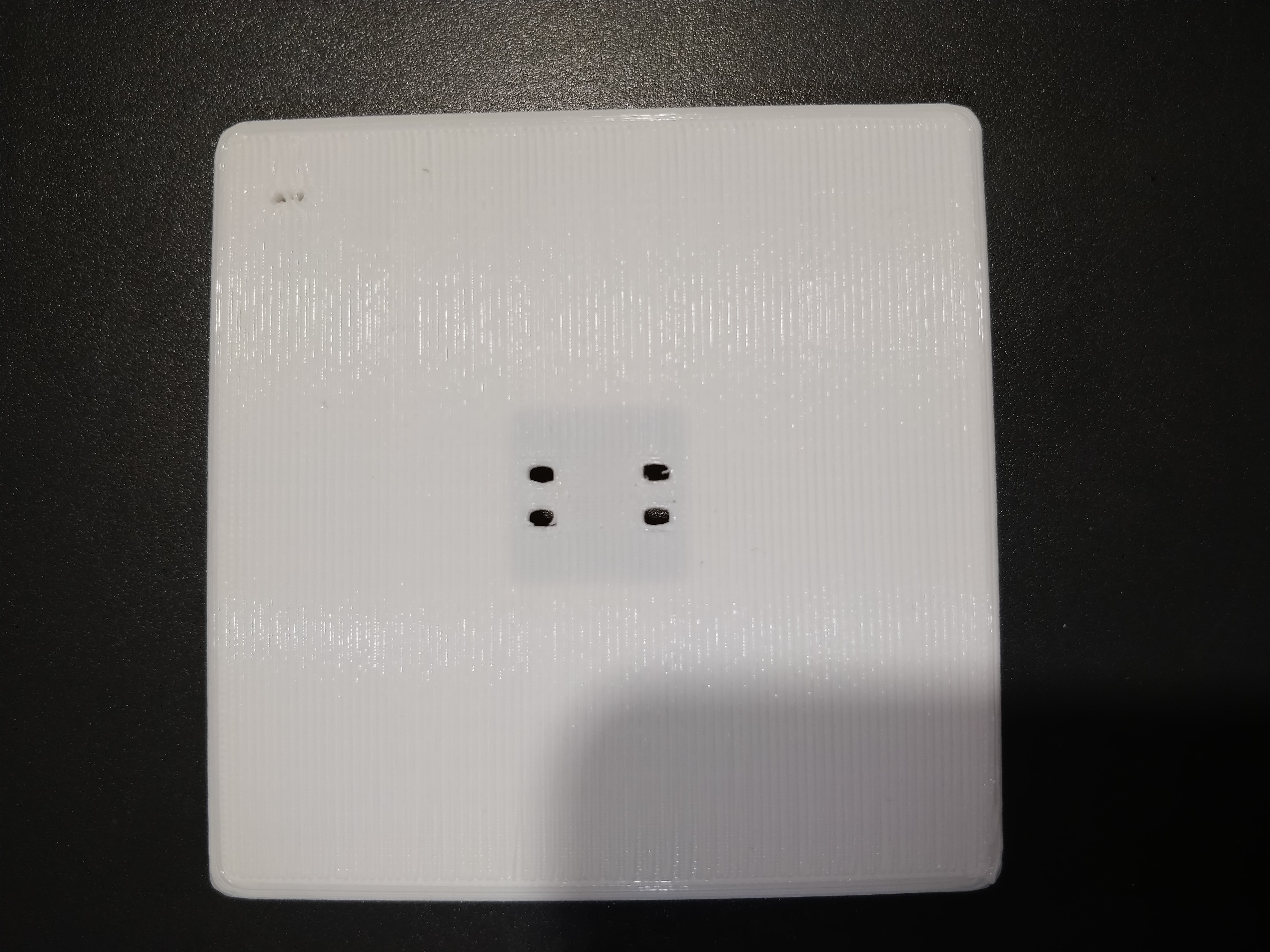
As soon as I pressed the bottom holder into the main lid, one of the 0.8mm thin (too thin) snap fits broke off. I realized after thinking for an embarrassingly long 5 minutes that the recessed design was entirely unnecessary - I could have a flat top and just make the button cap taller. D'oh!
![]()
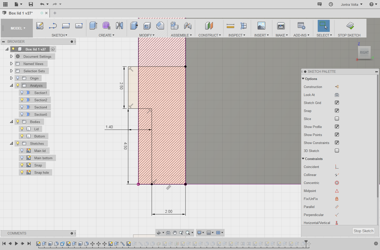
The square groove on the underside is meant to fit a small protoboard where the button legs are soldered. The legs are too short to fit through the 3.2mm shell and a board. There's no groove for the LED holes (top) since the legs are long enough. Snap fits are now 1.2 mm thick, up from 0.8mm.
-
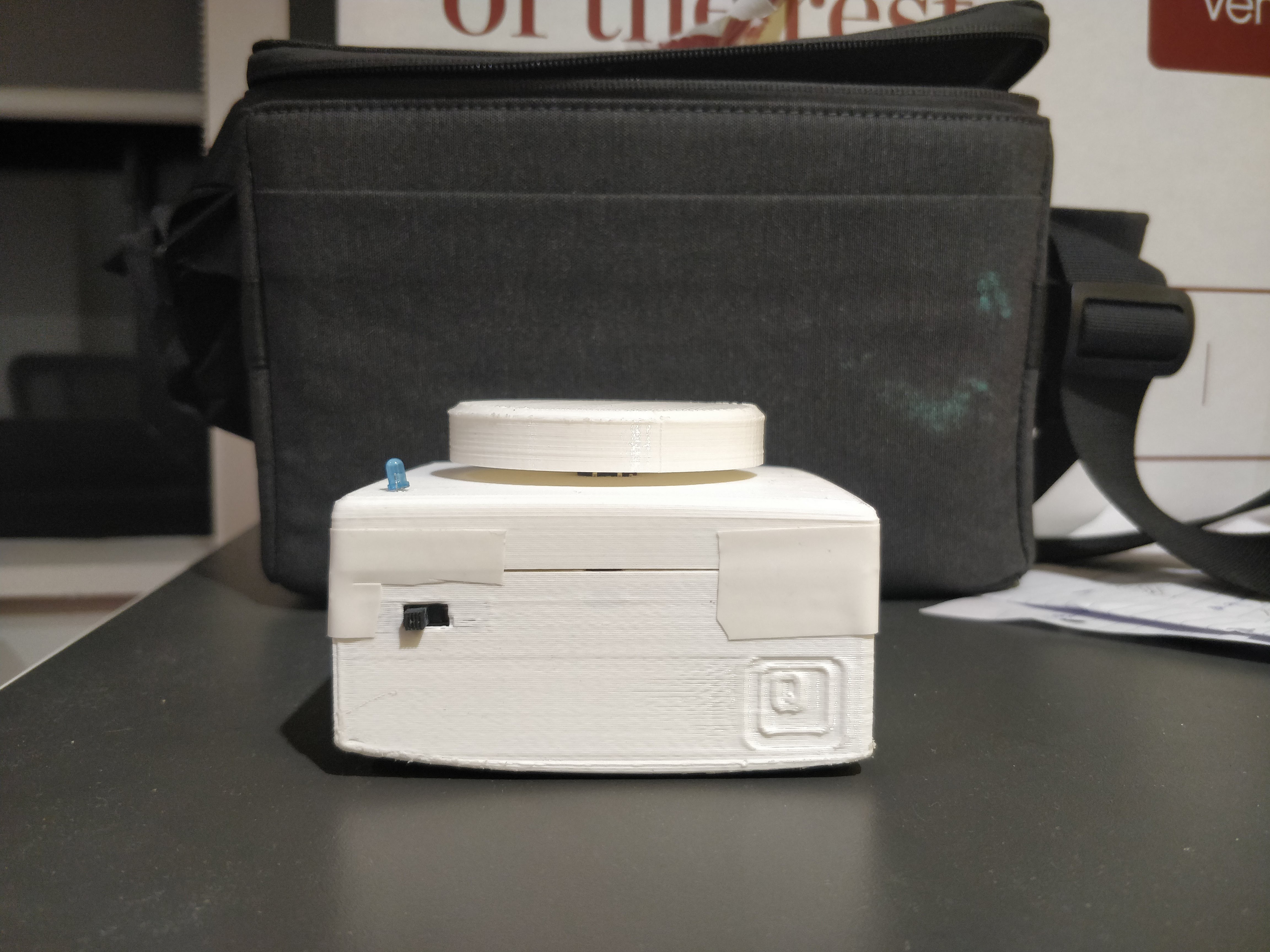
6Body design, part 1
The main body was designed to be 35mm tall, enough for the NodeMCU plus protoboard with header pins to fit comfortably inside. The NodeMCU is mounted with M3 screws into nuts superglued into standoffs. There are 2 holes for the microusb port and a small switch to turn off and on battery power.
![]()
There's a tiny engraved logo on the wall, which I added with Insert -> Insert SVG.
The most fiddly part of this to get right was the cantilever fit, which I only managed to be satisfied with in the 4th box.![]()
![]()
All .stl files are in the project home page.
-
7Body design, part 2
Unfortunately there was serious warping on box #1's bottom due to the build plate's adhesive wearing off. You can tell when this happens, at least on the Makerbot Replicator+, when it does not take any effort to remove the model from the build plate.
![]()
Box #1 was in usable shape, apart from the 1.2mm snap fits breaking off again from the redesigned lid - the next run will attempt 1.6mm thick cantilevers. The M3 nuts in particular fit quite snugly. I can't remember the exact size I made the insets, but it was ~0.5mm wider than the width of the nut. You can also see above that I superglued the switch against the inner wall. Adding a small groove here prevented it from moving while I applied the glue.
-
8Populating the protoboard
The first thing I did was solder the NodeMCU directly to the board, thinking it would save time and vertical space. I immediately realised I had forgotten to solder a resistor in series with the LED so I desoldered all the pins. And then I soldered header rows so that it would be easy to add components I had forgotten, or repurpose the ESPs.
I forgot to take pictures of the board itself, but the layout itself is super simple - 3 GND wires, 1 VIN wire, 2 GPIO wires. One of the GPIO wires has a resistor for the LED. I had no idea what these were rated for so I assumed 20mA, 0V threshold (no idea what this would be either, my classes at uni used 0.7V) and picked the resistor closest to 3.3 / 0.02 = 165 ohms, which turned out to be a 150 ohm. It lights pretty brightly, hasn't burned yet.
A toggle switch breaks connection from the batteries to VIN. -
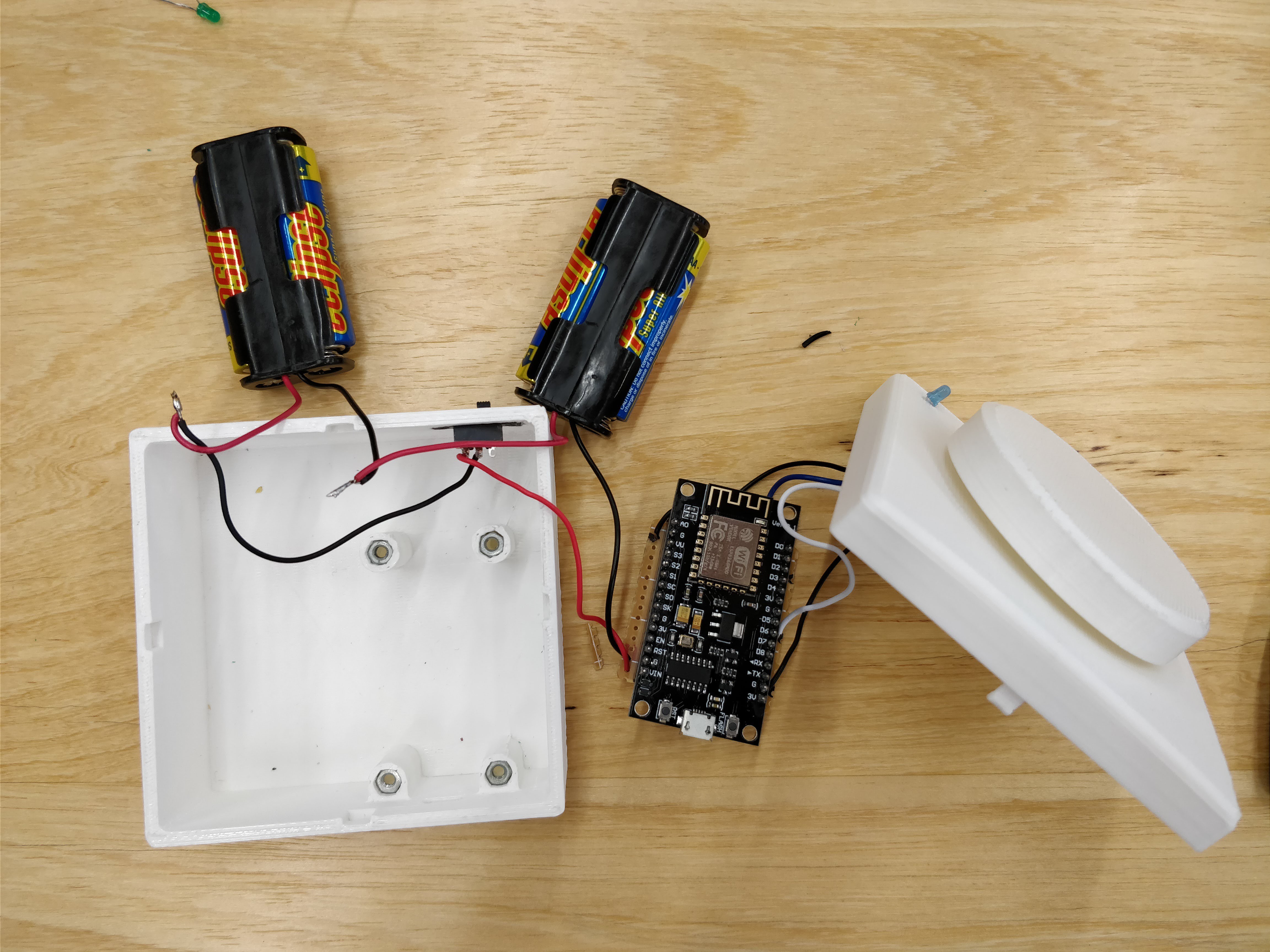
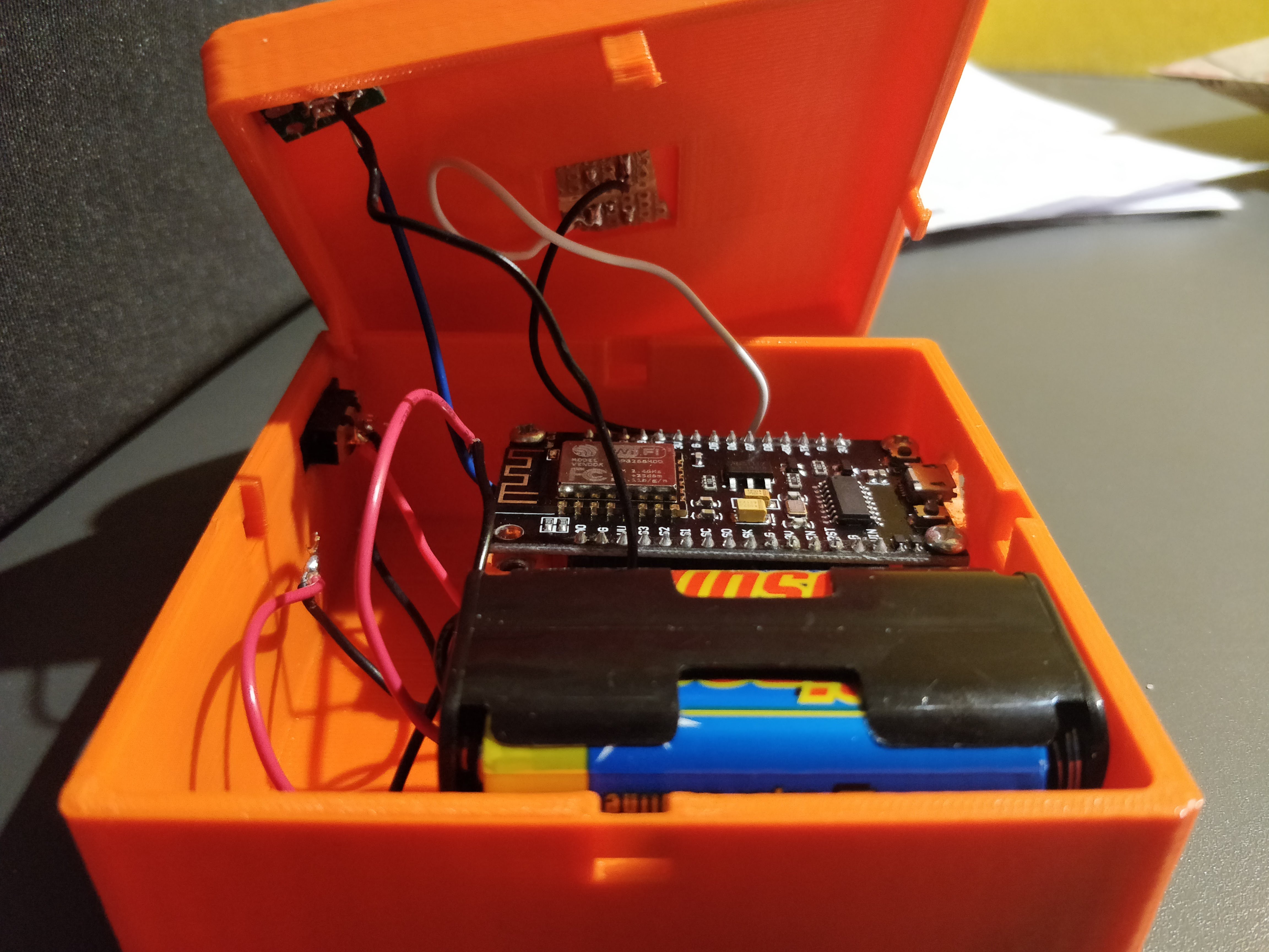
9Putting everything together
It was fairly easy to solder all the parts together. The only slightly frustrating part was soldering wires to the board underneath the button, since the wires couldn't go through the holes.
![]()
![]()
You can clearly see the warping on the bottom here. Since the snap-fits broke off I just taped the lid and bottom together.
-
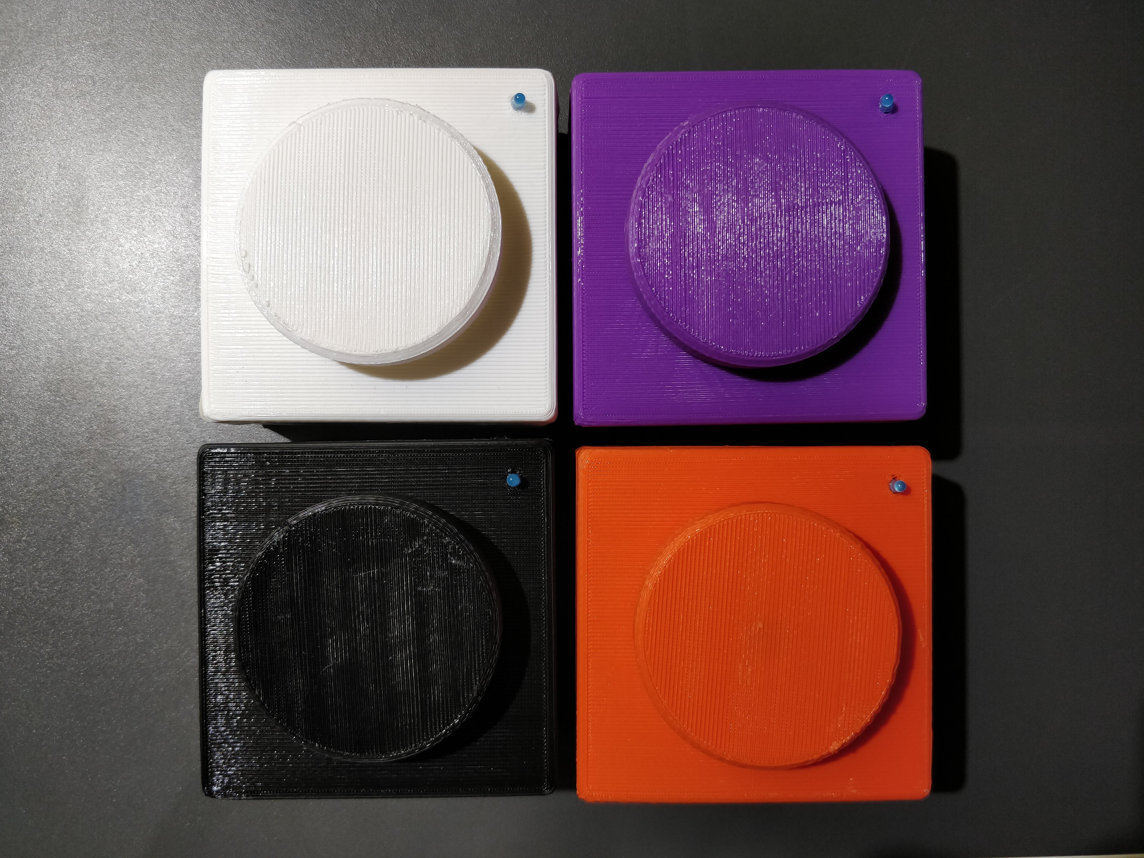
10Repeat
Printed and soldered everything again 3 more times. I ran out of 2 AA battery holders so I hacksawed a 4 AA holder in half and soldered wires to appropriate terminals. I also took care to flash each board with a different DEVICE_ID (see the .ino file) so that the desktop program would identify them as different buzzers.
![]()
![]()
Only thing left to do is run a quiz night!
Quiz-o-matic wireless buzzers
Wireless buzzers for trivia nights using ESP8266
Discussions
Become a Hackaday.io Member
Create an account to leave a comment. Already have an account? Log In.