Michael Graham
**COMING SOON TO CROWDSUPPLY! Follow here!**
2018HackadayPrize Final Video:
Introduction:
"Erector Set, Tinker Toys, Meccano, Lincoln Logs, LEGO ... All of these toys could be used to construct fanciful models of things, but not the things themselves. The game-changing 'toys' available to today's girls and boys are capable of making real things."
Of course that quote refers to things like 3d printers and laser engravers, but I saw it as an interesting challenge. A toy that can make real things... Why not customized coffee mugs? :)
TinyCNC PCB SPECS:
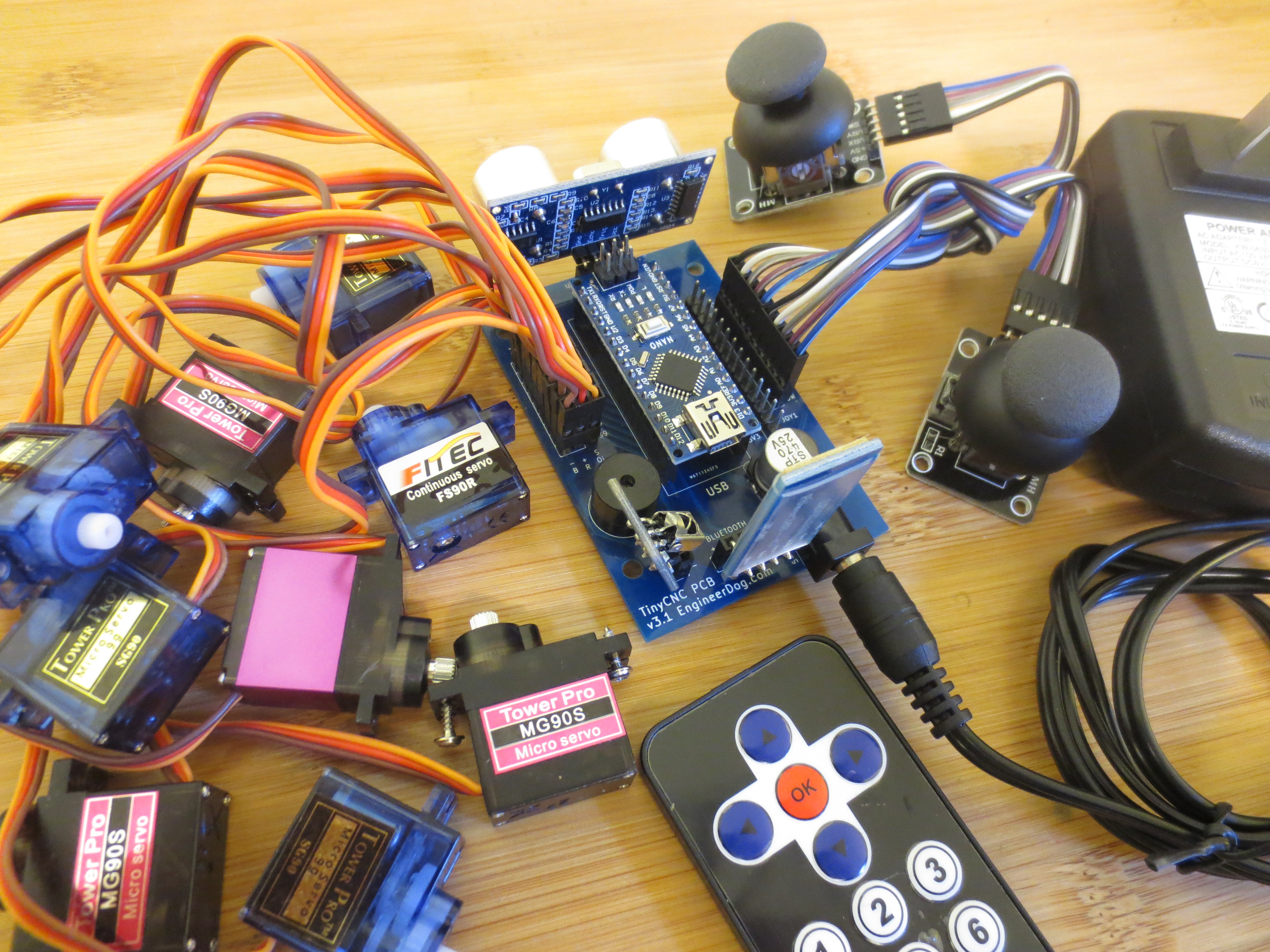
I found it necessary to make a customized PCB for this application. I could not find an off the shelf arduino based servo driver that did everything I wanted for the cost & size I needed. I ended up working with Scott Pierce and his open source pcb design to modify it for my needs. This is the result:
- Utilizes 1x Arduino Nano V3
- System Inputs: Up to 2X Analog Joysticks, Bluetooth (HC-06), Ultrasonic (HC-SR04), IR wireless remote, and of course micro-USB
- System Outputs: Up to 9x servo motors, built in Buzzer & LED.
- Power Requirements: 6VDC Wall Wart or 4X AA (Energizer Ultimate Lithium Recommended)
- Drives servos directly from battery power unhindered by the arduino and has extra wide copper traces to minimize board resistance.
Mug-O-Matic Tool Path Summary:
1. Create or find an image file you want to draw and convert it to an STL that is 0.1mm thick.
2. Use RepetierHost + Slic3r to convert the model into gcode.
3. Use Processing to send commands line by line from computer over usb.
4. Use Arduino with the Mug-O-Matic Gcode_reader sketch to decode commands.
.
So it draws on Mugs, But what else can you do with it?
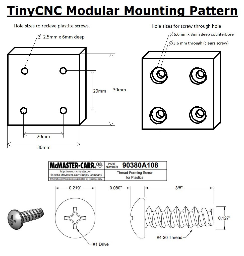
All parts in the TinyCNC Collection are compatible with 2 recurring design patterns. One is the 'snap on lid' that allows you to connect different base structures around the PCB. The other is a 20mm spaced hole pattern that allows for reconfiguration of all modules at 90 deg angles. So all parts either snap together or are connected by a single size of 'plastite' screw, which forms its own threads when installed.
All actuators are powered by 9g size servos, (SG90 extremely cheap, MG90s metal gear good quality, MG91 pro-quality, FS90R continuous rotation) all are physically interchangeable.
The servos are also great because they don't require motor drivers and they are physically small and yet still able to perform meaningful work. Up to ~0.5kg from the linear actuator in my simple experiment, though it varies directly with voltage.
Inspiration:
My idea was inspired in part by another interesting open source plotter robot design by MakerBlock. In particular, he and others developed (GRBL based) arduino code that allowed a robot to read g-code and plot with a marker using hobby servos, a task typically done with stepper motors. Great idea and perfect for making an ultra low cost robot that still had lots of functionality.
The other part of the inspiration was to emulate the famous Egg-bot, except with lower barriers to entry, more hackability, and to produce objects with more everyday appeal.
Linear Actuator Design:
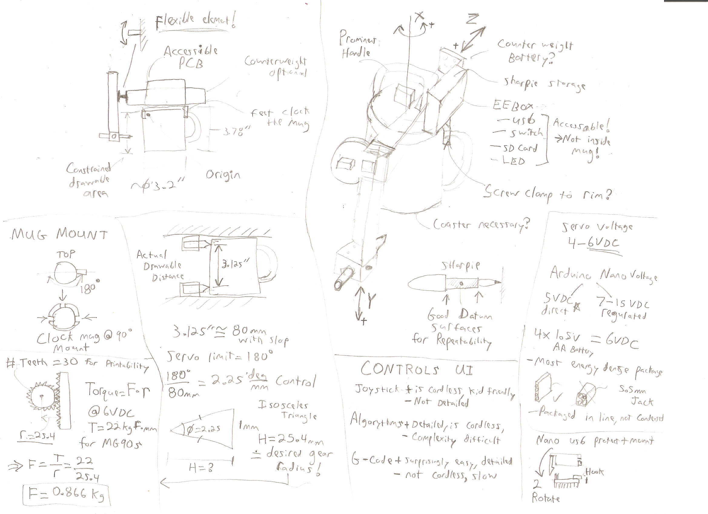
The key module in the Mug-O-Matic is the linear actuator assembly. I hadn't found anything available online so I designed one from scratch. Why a Rack & Pinion?
I choose a rack & pinion type actuator to keep the vitamins low and the movement speed fast. (As opposed to a slow leadscrew or pulley driven actuator with belts & bearings). Well for those reasons and the fact that hobby servos only have 180 degs of usable motion severely limits your options.
I had to do some math up front to size the gear to get the 80mm of motion I needed to draw on an entire 11 oz coffee mug. The effective diameter is the only variable that affects motion, tooth size did not, so I picked a large (easily printable) tooth size that maintained contact ratio around 2. The tooth mesh benefits from some of the assembly compliance to keep it tight enough to prevent backlash, but squishy to prevent sticking points.
Keeping it Tight:
For a drawing robot to be worth anything it needs to be rigid so you can draw straight lines. The challenge of designing a tight moving assembly without bearings is that to reduce slop you end up making it harder to drive, and hobby servos don't have much torque to waste.
Indeed, my research for an existing rack & pinion to start from yielded lots of wiggly/loose gear rack assemblies that are purpose built. Most of the machines I saw were hacked together, designed by folks gifted with software skills much greater than their mechanical design skills. I consider those projects to be fantastic works of art, rather than repeatable mechanically sound works of engineering. There is a limit to how much slop you can tune out of a machine.
So I had to design these models from scratch and during the iteration process I found it necessary to include some special compliance/adjustability features to facilitate reliably smooth motion. For those interested I wrote an article on my personal blog to share some of the design for assembly tips I used, "Design for Assembly Tips- Building a Better 3D Printed Linear Actuator".
To aid in that effort I included pockets/reservoirs along the moving surfaces to hold grease to further facilitate smooth motion.
Linear Actuator Physical Testing: (5 min mark)
Design History:
I began this work with research and very rough sketches until I came up with a plausible model. I leveraged the proven arduino case design & electronic aspects from my own previous work on SimpleSumo robots to give me a boost.
A good portion of the technical work on this project is detailed 3D modelling. The gear profile and CAD files were designed with Fusion 360. All parts were printed in my basement on my Prussia I3 MK2S. I use eSun PLA+ filament because it is super rigid (yet not brittle), dimensionally stable, does not require print rafts, and is human/environmentally safe. That last bit is particularly important for objects that may be printed in classrooms.
Iterating early & often was necessary to check my ability to maintain a smooth gear mesh, and to get an idea of how much performance I could squeeze out of the tiny servos. Through this iteration I realized the need for including adjustable/compliant features in the model and assembly designs to ensure that the models could be printed by other people. (I have a huge pile of old revision parts, good thing plastic is cheap!)
An interesting key feature: The Mug-O-Matic has one component 3d printed from a flexible filament. This joint attaches the vertical axis to the horizontal axis and provides compliance to keep the sharpie in contact with the mug at all times without overloading the driving motors.